

Bow Thrusters & Azimuth Jet Units — Tunnel Thrusters, CPP Blades and the White Gill Jet
Master bow thrusters on ships: tunnel construction, controllable pitch hub mechanics, bevel gear drive, header tank lubrication seals, diesel drive, and White Gill 360° jet thrusters for MEO exams.
1. Why Transverse Thrust Matters — The Manoeuvring Machine
Warning: Navigational and Electrical Criticality
Bow thrusters demand immense instantaneous electrical power—often 800 kW to 2,500 kW. Starting a thruster without adequate spinning generator reserve will trip the main switchboard on under-voltage or overcurrent, plunging the ship into a catastrophic blackout during confined-water pilotage.
A conventional ship’s rudder relies on the slipstream from the main propulsion propeller to generate a steering lift force. When a vessel slows down below 3 to 4 knots during berthing or canal navigation, water flow over the rudder drops drastically, rendering conventional helm control sluggish and ineffective. Strong beam winds acting against a modern container vessel’s massive deck container stack or a cruise ship’s towering superstructure generate lateral drift forces that readily overpower conventional tugs.
The transverse thruster, installed in the bow (and often in the stern as well), solves this problem by producing direct lateral thrust independent of the ship's forward speed. Installed as far forward as structural hull geometry allows, the thruster maximizes the turning moment arm around the ship's pivot point (Tmoment = Fthrust × Larm).
Pivot Leverage
Placed far forward in the bow, every tonne of lateral thrust acts across the longest possible distance from the ship's turning pivot, multiplying lateral swinging moment.
Tug Independence
Allows docking, undocking, and narrow basin turning without tug assistance, cutting harbour turnaround times and pilotage fees.
Dynamic Positioning (DP)
Essential for offshore supply vessels, drillships, and cable layers requiring computerized station-keeping against winds, tides, and currents.
Thrust generation follows Newton’s third law and momentum conservation: water is accelerated through the transverse tunnel by an axial-flow impeller, generating thrust:
F = ṁ · Δv = ρ · A · vjet · (vjet − vinlet)
Typical commercial bow thruster installations produce approximately 11 to 14 tonnes of lateral thrust per 1,000 kW (1,360 bhp) of applied power.
2. Tunnel Construction & Hydrodynamic Geometry
The thruster tunnel penetrates the ship's underwater hull from port to starboard. Because it pierces the outer hull shell and breaches the watertight boundary of the forward collision bulkhead zone, its construction is heavily regulated by Classification Societies.
Key structural requirements for the tunnel installation include:
- Tube Wall Thickness & Shell Doubler: The tunnel tube is fabricated from heavy rolled steel plate, generally 1.5 to 2.0 times the thickness of the adjacent hull shell plating. Heavy doubler rings or insert plates are welded at the shell junction where the tunnel penetrates the ship's skin.
- Internal Framing Continuity: Because transverse frames and web frames are severed to make way for the tunnel, heavy boundary web frames and vertical bracket plates are fitted to transfer panting and racking stresses into the hull structure.
- Rounded Entrance Fairings: Sharp 90° pipe edges would cause severe flow separation and vortex cavitation at the intake, cutting thrust by up to 25%. Tunnel openings are flared with a generous radius (r ≈ 0.08 × Dtunnel) to encourage smooth streamline ingress.
- Stainless Steel Tip Cladding: As propeller blade tips pass within a small radial clearance (typically 3 to 6 mm) from the tunnel wall at tip speeds exceeding 30 m/s, localized pressure drops create severe cavitation bubbles. The tunnel wall in way of the propeller swept zone is lined with a corrosion-and-erosion resistant AISI 316L stainless steel insert ring.
- Protective Grids (Debris Bars): Steel bars are welded across both tunnel apertures to prevent logs, mooring lines, ice blocks, or floating flotsam from entering and destroying the propeller blades. The bars are oriented horizontally (aligned with the forward streamline flow of the vessel) to minimize forward drag resistance when steaming at sea.
3. Controllable Pitch (CPP) vs Fixed Pitch (FPP) Thrusters
Commercial marine bow thrusters are built in two main configurations: Controllable Pitch Propeller (CPP) systems and Fixed Pitch Propeller (FPP) systems. The choice between them dictates prime mover selection and electrical switchboard architecture.
| Design Feature | Controllable Pitch (CPP) | Fixed Pitch (FPP) |
|---|---|---|
| Blade Mechanism | Blades rotate on crank discs actuated by an internal hydraulic servomotor piston inside the hub. | Blades are cast as a solid, monolithic one-piece bronze propeller keyed directly to the shaft. |
| Thrust Reversal | Reversal is instantaneous: blade pitch swings across neutral (zero thrust) from Port to Starboard. | Prime mover must be stopped, reversed, and re-accelerated in the opposite direction. |
| Prime Mover Duty | Constant-speed, unidirectional AC motor or direct-drive auxiliary diesel engine. | Variable Speed Drive (VFD) electric motor or reversible hydraulic motor. |
| Electrical Demand | Motor starts once in unloaded zero-pitch condition; current remains steady without repeated starting spikes. | Frequent start-stop-reverse cycles require expensive heavy-duty Variable Frequency Drives (VFDs) and large harmonic filters. |
| Mechanical Complexity | Higher: internal hydraulic seals, feedback rods, hunting gear, and Oil Distribution (OD) boxes. | Lowest: simple underwater pod with bevel gears and single-piece propeller. |
In a CPP thruster, the blade crank pins are driven by a sliding crosshead block coupled to a double-acting hydraulic piston inside the propeller hub. Hydraulic oil at 40 to 60 bar is supplied through concentric channels in the drive shaft via an Oil Distribution (OD) box mounted inboard.
When the bridge joystick demands "Port Thrust," hydraulic control valves admit high-pressure oil to the ahead chamber of the hub cylinder, pushing the piston forward and twisting the blade spindles via their eccentric crank pins. A mechanical or electronic feedback rod transmits the actual physical pitch angle back to the control amplifier, completing the closed-loop hunting circuit.
4. Prime Movers & Power Transmission
Bow thrusters require significant rotational power, supplied through three primary prime mover arrangements:
1. AC Electric Motor Drive
The most common commercial installation is a vertical squirrel-cage 3-phase AC induction motor mounted directly on top of the thruster drive column in the bow thruster room. Motors are typically 440 V for ratings up to 1,000 kW, and High Voltage (3.3 kV or 6.6 kV) for ratings exceeding 1,000 kW to reduce current draw and cable sizing.
- Starting Methods: Because direct-on-line (DOL) starting of a 1,500 kW motor draws 6 to 8 times full-load current (Istart ≈ 12,000 A), soft-starters, star-delta starters, or auto-transformer starters are mandatory to protect switchboard busbars from severe voltage sag.
- Zero-Pitch Starting Interlock: An electrical limit switch on the CPP feedback mechanism prevents the motor start contactor from energizing unless blade pitch is mechanically proved at absolute zero (unloaded).
2. Direct Diesel Engine Drive
On vessels with limited auxiliary alternator capacity—such as specialized tugs, dredgers, and smaller cargo vessels—a dedicated high-speed diesel engine (e.g., Caterpillar, Cummins, or MTU) is installed in the bow thruster space specifically to drive the thruster.
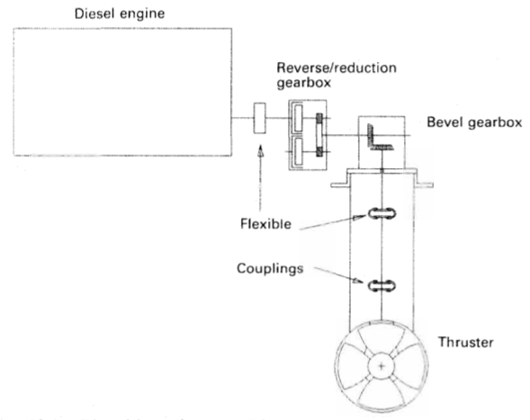
The diesel drive offers complete independence from the ship's electrical grid. The engine is started and brought up to operating speed while disengaged. A pneumatic or multi-plate hydraulic clutch is then gradually engaged to bring the thruster bevel gear train up to speed smoothly.
3. Hydraulic Motor Drive
Preferred on smaller offshore vessels, fishing vessels, and dynamic positioning thrusters where smooth infinitely variable speed is required without heavy electrical switchboards. A central hydraulic power pack (driven by PTO pumps on main engines or auxiliary diesels) supplies high-pressure oil (210 to 300 bar) to a bent-axis axial piston hydraulic motor mounted directly on the thruster column.
5. Drive Line, Bevel Gears & Header Tank Lubrication
The vertical input drive shaft transfers power down into the underwater pod through spiral bevel reduction gears. Spiral bevel gears are chosen for their smooth tooth engagement, low noise emission, and high torque-carrying capability.
The underwater gear pod cannot tolerate seawater contamination. Even 1% water in the gear oil destroys the hydrodynamic oil film on the highly stressed bevel gear teeth, leading to rapid pitting, scuffing, and catastrophic gear seizure.
The Gravity Head Defense Principle
To guarantee that seawater can never enter the pod, the lubrication system relies on a **gravity header tank** positioned well above the deepest operating waterline of the vessel:
Positive Pressure Differential
The tank is installed at such an elevation that internal static oil pressure inside the pod exceeds external seawater pressure by 0.3 to 0.5 bar (30 to 50 kPa) at all drafts.
Outward Leakage Direction
If a propeller shaft lip seal suffers wear or damage, positive differential pressure forces clean oil outward into the sea rather than allowing corrosive seawater into the gearbox.
Early Warning Instrumentation
The header tank is fitted with a magnetic float low-level alarm switch. Any drop in oil level warns the duty engineer of seal leakage long before gear damage occurs.
6. Shaft Sealing Systems & Water Ingress Defense
The propeller shaft passes through the gear housing into the sea and must remain sealed under continuous rotation, fluctuating lateral thrust loads, and varying immersion depths. The standard arrangement employs a multi-ring radial lip seal assembly.
Seal Materials
Sealing rings are molded from fluorocarbon rubber (FKM / Viton) or nitrile butadiene (NBR), tensioned around the shaft by garter springs to maintain radial contact pressure.
Shaft Wear Liner
Seals ride on a replaceable chrome-nickel stainless steel liner coated with plasma-sprayed ceramic or Tungsten Carbide, preventing seal grooves from cutting into the forged shaft.
Intermediate Drain Cavity
A void space between the forward seawater exclusion seal and the aft oil retention seal drains to a tell-tale pot in the thruster room, giving instant physical evidence of which seal is failing.
Danger: Environmental Compliance (VGP / Polar Code)
Under the US EPA Vessel General Permit (VGP) and international marine pollution rules, all bow thrusters with oil-to-sea interfaces must utilize Environmentally Acceptable Lubricants (EALs)—such as synthetic biodegradable esters or polyalkylene glycols (PAGs)—to avoid severe fines in the event of seal leakage.
7. The White Gill 360° Azimuth Jet Thruster
Conventional tunnel thrusters have one major operational limitation: their effectiveness drops drastically as the ship moves forward through the water. At steaming speeds above 4 to 5 knots, water rushing past the hull shears across the tunnel mouth, creating a low-pressure zone that severely curtails flow through the tunnel. By 8 knots, a conventional tunnel thruster produces virtually zero lateral force.
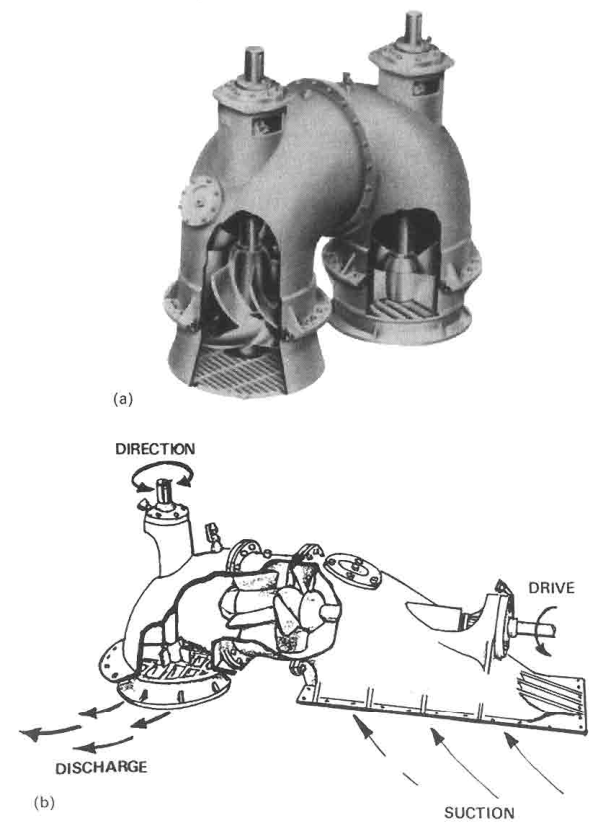
The **White Gill Thruster** is an advanced low-head, high-volume waterjet propulsion unit that eliminates this limitation entirely.
Working Principle & Mechanical Flow Path
Unlike a tunnel thruster which pierces both sides of the hull, the White Gill unit is mounted entirely within the hull structure:
- Keel Siphon Intake: Seawater is drawn into the unit through a flush intake grid located on the flat of the bottom keel plating. This ensures the unit remains fully submerged even when the vessel is in light ballast draft and pitching heavily in rough seas.
- Axial-Flow Impeller: A mixed-flow, high-volume axial impeller driven by an electric motor or diesel engine accelerates water upward through a short siphon bend.
- Rotary Deflector Discharge: The water discharges through a flush underwater nozzle containing curved deflector vanes. This deflector assembly is mounted on a heavy slewing ring geared to a worm drive motor, allowing it to rotate through a full 360 degrees.
| Operational Attribute | Standard Tunnel Thruster | White Gill 360° Jet Thruster |
|---|---|---|
| Thrust Vector Direction | Port or Starboard only (180° opposed lateral axis). | Any angle through full 360° circle (ahead, astern, athwartships, diagonal). |
| Performance at Ship Speed | Rapid thrust decay above 3 knots; ineffective above 6 knots. | Remains fully effective at speed; can steer or brake the vessel at 10+ knots. |
| Emergency Propulsion | None (cannot propel ship forward). | Capable of acting as an **independent take-home auxiliary propulsion device** (3 to 5 knots) if main engine fails. |
| Ballast Draft Sensitivity | Tunnel easily emerges and sucks air in light draft / heavy swell, causing severe cavitation. | Intake and discharge are flush with bottom keel; never draws air. |
8. Operational Watchkeeping, Interlocks & Overhaul
Mandatory Safety Interlocks
Because of the severe thermal, mechanical, and electrical stresses involved, bow thruster control circuits incorporate fail-safe protective trips:
- Zero Pitch Start Interlock: Prevents motor start unless pitch feedback confirms the propeller blades are flat at 0° pitch.
- Generator Reserve Interlock: In integrated Power Management Systems (PMS), the thruster start push-button sends a load request signal. The PMS automatically starts an additional diesel generator, synchronizes it to the main switchboard, and only releases the start circuit when adequate kW spinning reserve is confirmed.
- Maximum Continuous Run-Time Timer: Many electric motors are rated for intermittent duty (e.g., S2-30 min). A timer sounds a bridge warning if continuous full-pitch operation exceeds thermal limits.
- Hydraulic Header Tank Level Alarm: Sounds immediately if gravity tank level drops, warning of seal failure.
- Motor High Stator Temperature & Bearing High Temp Alarms: Sensed via PT100 RTDs embedded in motor windings and gearbox thrust pads.
Drydock Overhaul & Maintenance Checklist
During scheduled drydocking (typically every 5 years), the engineering team and Class surveyor inspect the following critical points:
| Inspection Item | Tolerances & Inspection Criteria | Failure Consequences if Ignored |
|---|---|---|
| Blade Tip Clearance | Measure with long feeler gauges at four quadrants; typically 3.0 mm to 6.0 mm depending on tunnel diameter. | Excessive clearance causes tip vortex loss; insufficient clearance causes blade strike under hull flexing. |
| Bevel Gear Backlash & Contact Pattern | Check tooth contact with engineer's blue and measure circumferential backlash with dial indicator (typically 0.35 to 0.55 mm). | Incorrect backlash leads to gear tooth chipping, severe whine, and ultimate fracture under peak reversing shock. |
| Shaft Lip Seals Renewal | Replace all inner and outer Viton lip seals; inspect chrome liner for wear grooves (<0.1 mm allowable, otherwise remachine/offset). | Seawater ingress into bevel gear pod; immediate emulsification of synthetic gear oil. |
| Sacrificial Anodes & Tunnel Grids | Weigh and replace zinc/aluminium anodes in tunnel; inspect grid bar welds for fatigue cracks from flow vibration. | Galvanic attack on tunnel steel plate; loosened grid bar passing through propeller blades. |
Found a mistake, or something unclear?
Report it in a few seconds — it goes straight to the editors.