

Reverse Osmosis (RO) Desalination Plants — Membranes, High-Pressure Pumping & Water Quality
Master marine reverse osmosis (RO) plants: osmotic pressure physics, spiral-wound membranes, 65-bar pumps, energy recovery, calcite filters, and CIP cleaning for MEO exams.
1. Osmotic Pressure Physics & The RO Operating Philosophy
Warning: The Limitations of Thermal Evaporators
Traditional marine vacuum freshwater generators (FWGs) boil seawater at low temperatures (45°C to 50°C at -0.9 bar vacuum) using waste heat extracted from the main engine jacket cooling water. However, modern ultra-long-stroke electronic engines operating in slow-steaming mode emit drastically reduced jacket waste heat. Furthermore, thermal evaporators cannot run inside harbors, canal transits, or within 20 miles of land due to estuary bacterial contamination and environmental regulations. Reverse Osmosis operates on electrical power, generating hundreds of tonnes of potable water on demand, anywhere in the world.
Natural Osmosis vs. Reverse Osmosis
Osmosis is a fundamental natural physical phenomenon. When two solutions of different salt concentrations are separated by a semi-permeable membrane (a barrier permeable to water molecules but impermeable to dissolved salt ions), water spontaneously diffuses from the dilute side into the concentrated saline side to equalize chemical potentials.
The hydrostatic pressure difference at equilibrium is the Osmotic Pressure (Π). For standard open-ocean seawater containing approximately 35,000 mg/L (ppm) Total Dissolved Solids (TDS) at 25°C, natural osmotic pressure is calculated via the van ’t Hoff relation:
Π = i · M · R · T ≈ 25 to 28 bar (2.5 to 2.8 MPa)
To reverse this natural flow and extract pure freshwater from seawater, an external hydraulic pump must apply a pressure significantly higher than the natural osmotic pressure. The effective pressure driving water through the membrane is the Net Driving Pressure (NDP):
NDP = Papplied − ΔΠ − ΔPfriction
In practice, commercial marine RO plants operate at 55 to 70 bar gauge (5.5 to 7.0 MPa). This immense pressure overcomes the baseline 28 bar osmotic barrier, accounts for the rising osmotic pressure of the concentrated reject brine (which reaches ~45 bar as water is extracted), and overcomes membrane hydraulic friction, producing an abundant stream of pure permeate.
2. Multi-Stage Seawater Pre-Treatment & Conditioning
Danger: The Fragility of Reverse Osmosis Membranes
The active separation layer of a modern RO membrane is an aromatic polyamide film only 0.2 microns (0.0002 mm) thick. Suspended silt, rust flakes, colloidal clay, biological bacteria, or oil droplets will physically plug the microscopic pores within hours. Even worse, free chlorine dissolved in seawater will chemically oxidize and permanently destroy the polyamide molecular polymer chains, ruining tens of thousands of dollars of membrane elements instantly.
The Multi-Barrier Pre-Treatment Train
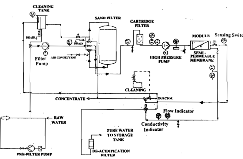
Seawater drawn from the ship’s sea chest passes through a rigorous sequence of physical and chemical conditioning stages before reaching the high-pressure pump:
1. Dual-Media Sand Filter
Seawater flows through a pressurized vessel containing graded gravel, fine quartz sand, and anthracite coal. Removes large suspended solids, sand, algae, and macroscopic plankton down to 20 to 50 microns. Backwashed regularly with seawater.
2. Cartridge Micro-Filters
Dual-stage disposable pleated polypropylene cartridge filters: a 5-micron pre-filter followed by a 1-micron absolute polishing filter. Protects the high-pressure pump plungers and membrane channels from abrasive silt.
3. Antiscalant Chemical Dosing
As pure water is extracted, calcium carbonate (CaCO3), calcium sulphate (CaSO4), and barium salts concentrate beyond saturation. Precision metering pumps inject specialized polymeric antiscalant (e.g. polyphosphates) to distort crystal formation and prevent scale adhesion.
4. Dechlorination (Sodium Bisulphite)
If sea chests are dosed with sodium hypochlorite for marine growth prevention (MGPS), the free chlorine must be eliminated. Sodium bisulphite (SBS, NaHSO3) is dosed into the feed line to reduce free chlorine to absolute zero (< 0.02 ppm).
The Silt Density Index (SDI) Quality Standard
Engineers evaluate pre-treatment water quality using the standardized Silt Density Index (SDI15) test. Seawater is passed through a 0.45-micron test filter pad at 2.07 bar (30 psi) pressure, measuring the time required to collect 500 mL initially (t0) and after 15 minutes of continuous filtration (t15):
SDI15 = 1 − (t0 / t15)15 × 100%
For spiral-wound polyamide membranes, SDI15 must strictly be below 3.0 (and never exceed 5.0). Operating an RO plant with SDI > 5.0 causes rapid colloidal fouling, requiring premature acid chemical cleaning.
3. High-Pressure Pumping & Energy Recovery Devices (ERD)
Generating the 55 to 70 bar hydraulic pressure needed to drive reverse osmosis requires specialized high-pressure pumps built from materials that resist both extreme mechanical stress and saltwater crevice corrosion.
High-Pressure Pump Architectures
- Triplex Plunger Pumps (Positive Displacement): Used on small-to-medium shipboard RO units (capacity 10 to 60 tonnes/day). Three solid ceramic (aluminium oxide) plungers reciprocate inside a forged Super Duplex stainless steel (UNS S32750) liquid head. Driven by an electric motor through an oil-bath crankcase, they deliver high volumetric efficiency (> 90%) independent of pressure variations. Fitted with pulsation dampeners to absorb cyclic pressure ripples.
- Multi-Stage Centrifugal Pumps: Used on large cruise ships and passenger vessels (capacity 100 to 1,000+ tonnes/day). Multiple closed impellers mounted in series inside a high-pressure barrel casing. Features smooth, vibration-free flow without pulsations, but requires variable frequency drives (VFD) for pressure regulation.
Energy Recovery Devices (ERD) — Slashing Power by 60%
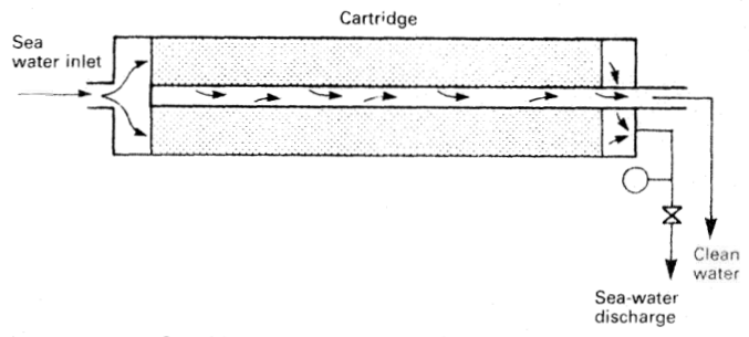
In a typical seawater RO plant, only 30% to 40% of the feed seawater is recovered as freshwater permeate. The remaining 60% to 70% is discharged as concentrated reject brine. Crucially, this reject brine leaves the membrane pressure vessels at 50 to 65 bar, retaining virtually all the hydraulic pressure energy originally imparted by the high-pressure pump.
Early marine RO plants simply vented this high-pressure brine through a throttling needle valve overboard, wasting enormous electrical energy. Modern installations incorporate Isobaric Pressure Exchangers (PX) or Hydraulic Turbochargers:
Isobaric Pressure Exchanger (PX)
Utilizes a precision-machined ceramic rotor spinning freely inside a ceramic sleeve. High-pressure reject brine directly contacts incoming low-pressure seawater in axial rotor ducts, transferring pressure energy with over 96% net hydraulic efficiency.
Hydraulic Turbocharger
High-pressure brine expands through a Pelton turbine runner, driving an auxiliary centrifugal booster impeller mounted on the same shaft. The booster assists the main feed pump, reducing main motor electrical load.
Specific Energy Slashed
Energy recovery devices slash specific electrical consumption from an unsustainable 7.5–9.0 kWh/m³ down to an ultra-efficient 2.8–3.5 kWh/m³ of freshwater produced.
4. Spiral-Wound Thin-Film Composite (TFC) Membrane Architecture
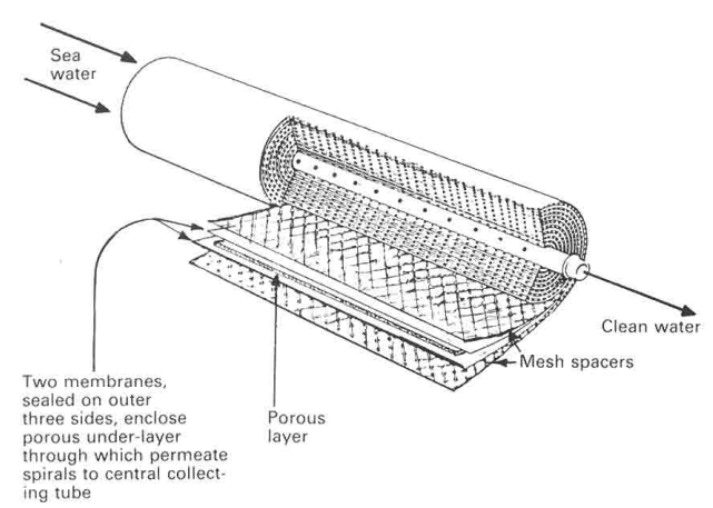
To pack hundreds of square meters of delicate membrane surface area into a compact shipboard footprint, marine reverse osmosis plants utilize Spiral-Wound Thin-Film Composite (TFC) Membrane Elements housed inside heavy cylindrical Glass-Fiber Reinforced Plastic (FRP) pressure vessels.
The Multi-Layer Sandwich Construction
A spiral-wound element consists of multiple membrane leaves bonded along three edges to form sealed envelopes ("leaves"), wrapped tightly around a central perforated tube:
- Active Separation Barrier (0.2 µm): A semi-aromatic polyamide polymer cross-linked via interfacial polymerization. Its sub-nanometer molecular pore structure allows neutral water molecules to pass through while electrostatically rejecting charged sodium (Na⁺), chloride (Cl⁻), magnesium (Mg²⁺), and sulphate (SO₄²⁻) ions.
- Microporous Support Layer (40 µm): An asymmetric polysulfone substrate with progressively larger pores that provides mechanical compressive support to the fragile polyamide skin.
- Reinforcing Backing (120 µm): A non-woven polyester fabric web providing tensile strength under 70 bar operating pressure.
- Feed Spacer Mesh: A plastic netting inserted between adjacent membrane leaves. It maintains open flow channels for high-pressure seawater and induces turbulence to sweep concentrated salt away from the membrane face.
- Permeate Tricot Carrier: A porous fabric inside the sealed leaf envelope that collects pure freshwater molecules and conducts them spirally inward to the central perforated tube.
Membrane Hydraulic Performance Equations
| Parameter | Mathematical Formula | Standard Marine Operating Value |
|---|---|---|
| Water Permeate Flux (Jw) | Jw = A × (ΔP − ΔΠ) | 12 to 20 litres / (m² · hour) (LMH). Driven strictly by net effective pressure. |
| Salt Rejection Ratio (R) | R = [ 1 − (Cpermeate / Cfeed) ] × 100% | ≥ 99.4% to 99.8% (Reduces 35,000 ppm seawater down to < 200–350 ppm). |
| Recovery Ratio (Y) | Y = (Qpermeate / Qfeed) × 100% | 30% to 40%. Kept low intentionally to sweep concentrated salts away before supersaturation occurs. |
5. Permeate Post-Treatment & Calcite Remineralization
Warning: The Danger of Raw Permeate ("Hungry Water")
Freshwater emerging directly from the membrane core tube is not ready for human consumption or shipboard distribution. Because the membrane rejects all minerals while allowing dissolved carbon dioxide gas (CO2) to pass through freely, raw permeate is naturally acidic (pH 5.5 to 6.2) and completely devoid of minerals. This "hungry water" aggressively leaches heavy metals, corrodes steel distribution pipework, dissolves copper calorifier tubes, and tastes flat and unpalatable.
Post-Treatment Conditioning Stages
Before entering the ship’s potable water holding tanks, raw permeate undergoes three mandatory treatments:
- Re-Hardening & De-Acidification (Calcite Filter Bed):
Permeate flows upward through a pressurized bed of crushed calcium carbonate (calcite, CaCO3) or magnesium-rich dolomite (CaCO3 · MgCO3). The acidic dissolved CO2 in the water reacts with the mineral bed:
CaCO3 + CO2 + H2O → Ca(HCO3)2
This reaction neutralizes the acid, raises the pH to a stable, non-corrosive 7.4 to 8.2, and introduces 30 to 50 ppm of essential calcium and magnesium hardness ions, imparting a crisp, natural drinking water taste.
- Automated Solenoid Salinity Dump Valve:
A continuous high-frequency toroidal electrical conductivity sensor monitors the permeate line. If membrane degradation occurs and salinity exceeds 500 ppm TDS (WHO drinking limit) or 10 ppm TDS (when feeding technical boiler water), the automated three-way solenoid valve de-energizes, diverting the off-spec water overboard and sounding an audible alarm in the ECR.
- Disinfection & Sterilization:
To eliminate any residual bacteria or viruses and satisfy World Health Organization (WHO) and ILO Maritime Labour Convention (MLC 2006) health standards, the water passes through an Ultraviolet (UV) Sterilizer (irradiating water with 254 nm germicidal UV-C light at > 40 mJ/cm²) followed by controlled residual sodium hypochlorite chlorination (0.2 to 0.5 ppm free chlorine) or a silver-ion generator.
6. Clean-In-Place (CIP) & Membrane Preservation
Over months of operation, membrane pores accumulate fine colloidal silt, organic slime, biological biofilms, and inorganic mineral scales. A structured Clean-In-Place (CIP) chemical rejuvenation protocol restores original flux without removing membrane elements from their pressure vessels.
Shutdown Freshwater Flushing (Anti-Osmosis Protection)
Danger: Automatic Flush on Every Plant Stop
When the high-pressure pump stops, if concentrated reject brine (~60,000 ppm) remains trapped inside the pressure vessel, reverse osmosis immediately turns into forward osmosis. Water from the low-pressure permeate line is sucked backwards across the membrane into the brine space with immense suction force, which can delaminate and blister the thin polyamide film. The RO automated controller must execute an automatic low-pressure permeate flush for 5 to 10 minutes upon every shutdown, displacing all brine with pure freshwater.
When is Chemical CIP Cleaning Required?
A CIP chemical clean is initiated when normalized operating logs reveal any of the following threshold deviations:
- Permeate Flux drops by 10% to 15% at constant feed pressure and temperature.
- Differential Pressure (ΔP) across vessel increases by 15% to 20% (indicating feed spacer mesh fouling).
- Permeate Salinity increases by 15% (indicating membrane scaling or concentration polarization).
The Two-Stage Chemical CIP Procedure
| CIP Stage | Chemical Cleaning Solution | Target Fouling Mechanism | Operational Procedure |
|---|---|---|---|
| Stage 1: Acid Cleaning (Low pH) | 2.0% Citric Acid or 0.5% Phosphoric Acid (pH adjusted to 2.0 to 3.0) | Inorganic mineral scale: calcium carbonate, iron oxides, metal hydroxides | Recirculate acid solution at 35°C to 40°C and low pressure (2–3 bar) for 60 min; soak for 1 hour; flush thoroughly with permeate to neutral pH. |
| Stage 2: Alkaline Cleaning (High pH) | 0.1% Sodium Hydroxide (NaOH) + 0.1% Na-EDTA chelate (pH adjusted to 10.5 to 11.5) | Organic biofilms, bacterial slime, algae, and oil residue | Recirculate alkaline solution at 35°C for 60 min; soak for 2 hours to dissolve slime; flush with permeate until neutral pH is confirmed. |
| Long-Term Preservation | 1.0% Sodium Metabisulphite (SMBS) solution (Na2S2O5) | Prevents biological bacterial and fungal growth during layup | Circulate through vessels prior to drydocking or shutdowns exceeding 5 days. Protects membranes from microbial decomposition. |
7. Watchkeeping Diagnostics & Troubleshooting Matrix
Operating a marine RO plant demands continuous monitoring of temperatures, pressures, and flow rates. Because seawater viscosity and osmotic pressure change with ocean temperature, performance must always be evaluated relative to baseline normalized curves.
| Observed Symptom | Probable Root Cause | Engine Room Diagnostic & Remedial Action |
|---|---|---|
| Permeate Salinity Suddenly Spikes (> 500 ppm) | O-ring interconnect seal between membrane elements cracked; membrane mechanical rupture | Conduct "probe test": insert conductivity probe along central permeate core tube to pinpoint which specific element has failed. Replace cracked EPDM interconnector O-rings or renew ruptured element. |
| Low Permeate Flow with High Feed Pressure | Cold seawater temperature (< 10°C); membrane colloidal fouling | Verify water temperature: flux drops ~3% per 1°C temperature drop. If water is warm, check SDI; perform two-stage CIP chemical clean. |
| High Differential Pressure (ΔP) Across Pressure Vessel | Heavy particulate clogging in feed spacer mesh; biofouling | Differential pressure exceeds 1.5 bar per vessel. Backwash sand filter; replace 1-micron cartridges; execute alkaline CIP wash. |
| High-Pressure Pump Cavitation & Severe Vibration | Cartridge filter plugged; booster pump suction strainer clogged | Check ΔP gauge across cartridge filters. If ΔP > 0.8 bar, suction pressure to HP pump drops below NPSH required. Replace cartridge filter elements immediately. |
| Permeate Flow and Salt Rejection Both Plummets Irreversibly | Chlorine oxidation attack from ship MGPS anti-fouling system | Check free chlorine upstream of HP pump with DPD chemical test kit. If chlorine is detected, sodium bisulphite dosing failed. Damaged polyamide membranes cannot be cleaned and must be scrapped. |
Potable Water Logbook & Testing Rules
- Coliform Bacteria Testing: Microbial testing must confirm 0 E. coli colonies per 100 mL sample.
- Hardness & pH Checks: Test calcite bed effluent weekly (pH should be 7.4–8.2; total hardness > 50 mg/L as CaCO3).
- Pre-Filter Cartridge Differential: Renew 5µm and 1µm cartridges whenever differential pressure reaches 0.8 to 1.0 bar.
Standards & sources referenced
- MLC: International minimum working and living standards for seafarers.
- Conventions index
Found a mistake, or something unclear?
Report it in a few seconds — it goes straight to the editors.