

Axial Thrust Balancing & Balance Holes in Centrifugal Pumps
Master axial thrust balancing in centrifugal pumps: pressure distribution on impeller shrouds, balance holes and back wearing rings, pump-out vanes, balance drums, and balance discs.
1. Origin of Hydraulic Axial Thrust in Centrifugal Pumps
In every operating centrifugal pump, hydraulic pressures inside the casing create substantial forces acting on the rotating assembly. These forces are resolved into two vectors: radial thrust (acting perpendicular to the shaft due to non-uniform volute pressure distribution) and axial thrust (acting parallel to the shaft centerline).
Why Axial Thrust Generates Toward the Suction Eye
In an enclosed single-suction impeller, the liquid enters axially through the suction eye and is discharged radially at high velocity and pressure into the volute. Consider the pressure acting on the two external shrouds of the impeller:
| Impeller Face | Effective Surface Area Exposed to Liquid | Average Pressure Acting on Surface | Resultant Force Direction |
|---|---|---|---|
| Back Shroud (Rear) | Full circular disc area: from the outer diameter down to the shaft hub diameter (Aback ≈ π/4 × (D22 − Dhub2)). | High discharge pressure (Pd) bleeding from the impeller periphery, tapering slightly toward the hub. | Pushes the impeller forward toward the suction eye (→). |
| Front Shroud (Front) | Annular area only: from the outer diameter down to the suction eye diameter (Afront ≈ π/4 × (D22 − Deye2)). | Outer rim is at high discharge pressure (Pd), but the entire suction eye area (Aeye) is subjected only to low suction pressure (Ps). | Pushes the impeller backward toward the driver (←). |
Because the area of the back shroud exposed to discharge pressure is significantly larger than the annular area of the front shroud, the net static hydraulic force points overwhelmingly toward the suction eye:
Net Axial Thrust (Faxial) ≈ (Pdischarge − Psuction) × Aeye
In high-head boiler feed pumps or large ballast pumps, this unbalanced hydraulic load can exceed several tonnes of force. Without compensation, standard line ball bearings would be incinerated within minutes of operation.
2. Balance Holes & Back Wearing Ring Architecture
The standard method for counteracting axial thrust in single-stage closed-impeller pumps (including API 610 and ISO process pumps) is the combination of balance holes and a back wearing ring.
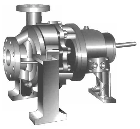
How Balance Holes Equalize Pressure:
- The Back Wearing Ring: A second wear ring is fitted on the rear shroud of the impeller, identical in diameter to the front suction wear ring. This ring establishes a close-tolerance running clearance between the rotating impeller and the stationary casing cover.
- The Balance Chamber: The volume trapped between the shaft sleeve, casing cover, and back wear ring forms an isolated cavity known as the balance chamber (or rear seal chamber).
- Balance Holes: Several holes (typically 4 to 8 holes, 6 mm to 15 mm in diameter) are drilled axially through the web of the back shroud, located radially between the hub and the back wear ring, discharging straight into the suction eye.
- Hydraulic Equalization: Any fluid that leaks across the fine clearance of the back wear ring into the balance chamber immediately escapes through the balance holes into the low-pressure suction eye. As a result, the pressure in the balance chamber drops to near suction pressure (Pchamber ≈ Psuction).
- Force Cancellation: Because both the front suction eye and the rear balance chamber now share the same diameter and near-identical pressure, the net static forces on the front and back shrouds cancel out almost completely!
Additional Benefit: Stuffing Box / Seal Chamber Pressure Reduction
By dropping the pressure behind the impeller from discharge pressure (e.g. 10 bar) down to suction pressure (e.g. 1 bar), balance holes drastically reduce the hydraulic pressure acting on the mechanical seal or gland packing. This lowers seal face heat generation and extends packing life tenfold.
3. Back Pump-Out Vanes (Radial Ribs)
In semi-open impellers, slurry pumps, and chemical transfer pumps where balance holes might easily clog with fibrous debris or suspended solids, pump-out vanes (also termed back vanes or scavenging ribs) are cast directly onto the rear face of the back shroud.
Operating Principle:
- As the impeller rotates, these radial back vanes impart angular velocity to the liquid trapped between the back shroud and the casing cover.
- The centrifugal force created by the spinning liquid throws the fluid outward away from the shaft hub toward the casing periphery.
- This centrifugal pumping action lowers the static fluid pressure near the shaft centerline, reducing the pressure acting on the back shroud and relieving axial thrust.
- At the same time, the centrifugal action prevents abrasive particles from entering the mechanical seal chamber or stuffing box throat bush.
Warning: Axial Clearance Sensitivity
Back pump-out vanes are extremely sensitive to axial running clearance (typically 0.4 mm to 0.7 mm). If the rotor shifts axially or if the casing gasket thickness changes during an overhaul, the pumping efficiency of the back vanes collapses, causing an immediate spike in axial thrust.
4. Double-Suction Impellers: Symmetrical Hydraulic Balance
For large-capacity marine pumps—such as sea water cooling pumps, general service pumps, and centrifugal cargo oil pumps—the double-entry (double-suction) impeller provides the ultimate mechanical solution for axial thrust.
- Complete Theoretical Balance: Because the impeller is structurally mirrored around its center plane, the axial forces produced on the left and right halves are identical in magnitude and opposite in direction.
- Half the Required NPSH: Liquid velocity through each suction eye is halved, significantly reducing the risk of cavitation.
- Light Thrust Bearings: The shaft thrust bearing only needs to handle minor transient imbalances caused by uneven piping elbows or slight casting variations.
5. Multi-Stage Centrifugal Pumps: Balance Drums & Automatic Discs
In high-pressure multi-stage pumps (such as boiler feed turbo-pumps operating at 40 to 100 bar), impellers are arranged in series. Because all single-suction impellers face the same direction, the axial thrust adds up across every stage. To neutralize this cumulative thrust, three sophisticated mechanisms are deployed:
A. Opposed Impellers (Back-to-Back Staging)
In two-stage or even-numbered multi-stage pumps, half the impellers have their suction eyes facing forward, while the remaining half have their suction eyes facing in the opposite direction. Long crossover passages route the discharge of one group to the suction of the next, naturally balancing the total axial force.
B. The Hydraulic Balance Drum (Balance Piston)
Fitted at the discharge end of the shaft after the final impeller stage:
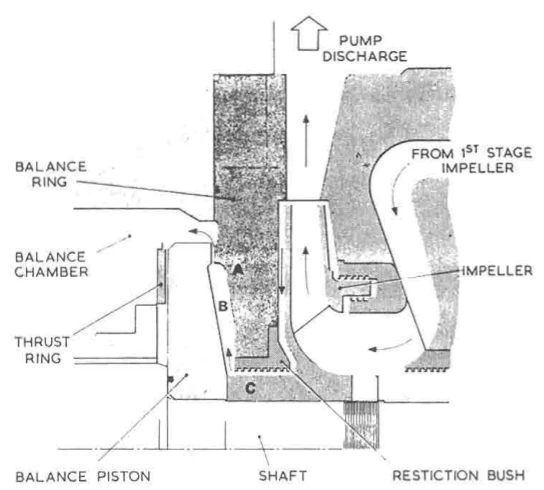
Operation:
- A cylindrical drum rotates inside a finely bored stationary casing bush.
- Full discharge pressure acts on the high-pressure side of the drum. Water leaks across the narrow annular bush clearance into the balance chamber on the other side.
- A dedicated leak-off pipe connects the balance chamber directly back to the pump suction tank or deaerator, keeping that side at suction pressure.
- The resulting pressure drop across the drum exerts a massive counteracting force pushing the rotor in the direction opposite to the cumulative impeller thrust.
C. Automatic Hydraulic Balance Disc
In modern water-lubricated high-speed turbo feed pumps, an automatic hydraulic balance disc provides self-regulating axial equilibrium without requiring any mechanical thrust bearing:
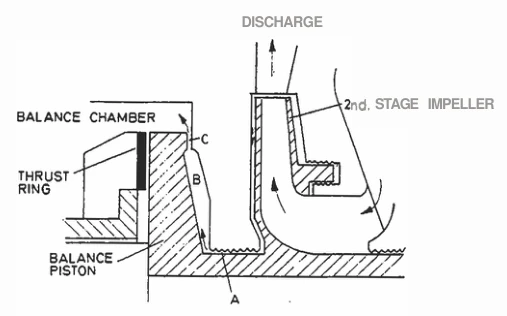
Self-Regulating Action:
- Water at discharge pressure passes through an annular restriction into space D behind the balance disc.
- The water then escapes through the minute axial gap F into a drain chamber connected back to pump suction.
- If impeller thrust causes the rotor to drift toward the suction end, gap F narrows. This restricts the water outflow, immediately causing pressure inside chamber D to rise.
- The elevated pressure acts against the balance disc, driving the rotor back away from the suction end until gap F re-opens.
- Conversely, if the rotor moves too far away, gap F widens, allowing water to escape freely. Pressure in chamber D drops, and the rotor drifts back.
- This feedback loop happens in milliseconds, holding the rotor dynamically suspended on a thin hydrodynamic fluid film without metal-to-metal contact!
6. Operational Failure Modes & Oral Exam Questions
Chief Engineer and MEO Class 4/2 examiners frequently focus on the failure modes of axial thrust balancing systems:
Danger: Failure Mode 1: Worn Back Wear Ring
Symptom: Rapidly overheating pump thrust bearings, severe motor overload, and vibration.
Cause: When the back wear ring clearance increases from abrasion or corrosion, high-pressure discharge liquid floods the balance chamber faster than the balance holes can evacuate it back to suction. Pressure behind the impeller jumps from suction level to near-discharge level, destroying the hydraulic balance and generating tonnes of unabsorbed thrust that burns out the ball/roller thrust bearing.
Danger: Failure Mode 2: Clogged Balance Holes
Symptom: Catastrophic thrust bearing collapse, metal shavings in bearing oil, and shaft scoring.
Cause: Marine growth, plastic debris, or boiler scale can plug the balance holes. Liquid leaking past the back wear ring cannot escape, causing full discharge pressure to build up in the rear chamber. This reverses or severely multiplies the net axial load.
Warning: Failure Mode 3: Blocked Balance Leak-Off Line
Symptom: Balance disc seizure, rotor locked against casing, boiler feed pump trip.
Cause: If the leak-off return valve to the deaerator/suction is accidentally closed or obstructed, the balance chamber cannot bleed off pressure. The balance disc cannot regulate gap F, leading to high-friction rubbing between the rotating disc and stationary face.
Key Oral Exam Questions:
Q: Why do balance holes reduce the pressure on the stuffing box?
A: Because balance holes connect the rear shroud cavity directly to the pump suction eye. The pressure in front of the shaft seal gland drops from discharge pressure (e.g. 8 bar) to suction pressure (e.g. 1 bar), minimizing packing wear and seal leakage.Q: What happens to a centrifugal pump if you renew only the front wear ring and leave a worn back wear ring?
A: The tighter front ring restores discharge pressure and flow, but the slack back ring allows massive leakage into the balance chamber, overwhelming the balance holes. The resulting high axial thrust will rapidly destroy the pump's thrust bearing. Always renew wear rings in matched pairs!
Found a mistake, or something unclear?
Report it in a few seconds — it goes straight to the editors.
- Pump Principles and Pump Types
- Centrifugal Pump Construction
- Axial Thrust Balancing & Balance Holes in Centrifugal Pumps
- Suction, NPSH, Cavitation and Priming
- Pump Curves and Speed Rules Made Simple
- Operation and Watchkeeping
- Pumping Systems Onboard
- Troubleshooting Index
- Overhaul, Inspection and Repair
- Safety and Emergency Actions
- Positive Displacement Pumps (Screw, Gear, Reciprocating) & Jet Eductors