
Charge Air Cooler — Density, Discipline & Fouling
Why cooled air makes more power, the 55°C ceiling and 20°C floor, and the checks that catch fouling first.
Key Principles at a Glance 5 points
- Cooling the charge packs more air mass per stroke — more fuel burned, more power, cooler exhaust and kinder pistons, liners and heads.
- Delivery lives between 55°C ceiling (density lost, exhaust climbing) and the 20–25°C dew-point floor (film wash-off, liner shock).
- Air-side fouling (oil-carbon-dust felt) and water-side scale (blocked tubes running hot) both announce via ΔT and pressure drop.
- Division plates multiply water passes; baffles support, direct, extend area and calm vibration — know which plate does what.
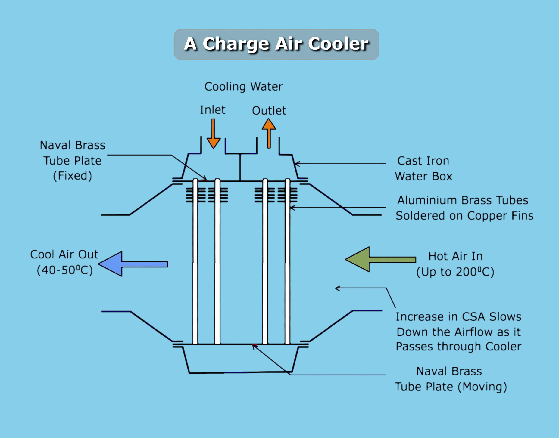
- Divergent inlet slows air for heat transfer, convergent outlet restores velocity; drains and grid separators handle what condenses anyway.
1. Cold Air Is Heavy Air
Turbocharger compression heats the charge — hot air is thin air, so the cylinder traps less mass, burns less fuel and makes less power while running hotter throughout. Cooling the charge to 40–50°C densifies it: more mass per stroke, more fuel per cycle, higher scavenge efficiency, lower exhaust temperature and gentler thermal loading on piston, rings, liner and head. Delivery past 55°C forfeits all of it; below 20–25°C the air crosses its dew point — condensate films wash liner oil away and cold shocks crack liners.
2. Siting & Build
Coolers sit between turbocharger outlet and scavenge manifold, hugging the cylinders with an insulated duct so cooled air cannot reheat on the way in. Aluminium-brass tubes solder-bonded into brass plates (flat tubes soldered, round tubes expanded) carry two seawater passes inside cast-iron water boxes; air crosses once outside finned blocks with intermediate anti-vibration supports. A sliding tube plate absorbs growth, anodes guard seawater spaces, cooling-water flow auto-trims to hold delivery temperature, and the free end seals on a rubber joint ring.
3. Fouling — Both Sides Attack
Air side: turbochargers inhale atmospheres — the fin block filters oil, carbon and dust into an insulating felt that throttles heat transfer and raises pressure drop, starving the engine. Water side: blocked tubes slow flow, wall temperatures climb, scale plates out fast. Either way the symptoms match: power, emissions and fuel burn worsen together.
Prove efficiency directly:
- Strong seawater in/out spread with small coolant-medium spread.
- Shell hot over warm over cool to the hand.
- Pump and bypass proved healthy.
- Manometer across the air side rising with fouling.
Plate duties to quote:
Division plates
Multiply water passes for efficiency.
Baffles
Support the stack, steer flow, extend area and kill vibration.
4. Velocity & Water Management
Slow wide air cools best, fast narrow air delivers best — so the inlet diverges (large slow cooling area) and the outlet converges (velocity restored), with the convergent outlet also trimming NOx-relevant mixing. Condensate is unavoidable near the dew point: drains report how much moisture leaves (or betray a water leak), and grid-type separators — paired angled blades using droplet inertia — strip up to 85% of entrained water before it reaches the liners.