Ship Sprinkler & Hypermist (Water Mist) Systems
Sprinkler regulation, bulb colours and the full 9-step test — plus hypermist water-mist for machinery spaces, with every pressure and flow.
Key Principles at a Glance 6 points
- Fixed sprinklers work by cooling and are required on cargo ships of 2000 GT and above and in category-A machinery spaces of 500 m³ and above, with two power sources for the sea-water pump, alarm and detection system and fresh-water pump.
- Each sprinkler section holds not more than 200 heads at 16 m² per head, maximum 4 m spacing and 2 m from the wall, delivering 100 L/min per head with at least 4.8 bar at the topmost head; sections are isolable by one stop valve outside the section.
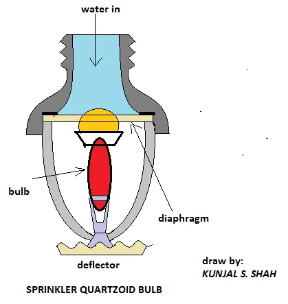
- Sprinkler bulbs are colour coded: orange 57 °C, red 68 °C, yellow 79 °C, green 93 °C and blue 141 °C; standard heads operate at 69–79 °C and high-temperature heads 30 °C above the maximum deckhead temperature.
- The 9-step sprinkler test proves zone isolation, NR-valve tightness, pressure-switch alarm, flow-switch alarm on bridge, engine room and fire control room, then air-purges and repressurises the section to gauge pressure.
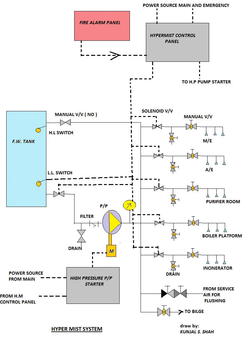
- Hypermist works by cooling and protects main engine, auxiliary engines, boiler, purifier and incinerator spaces without shutdown, in auto plus manual mode on UMS ships and manual mode on manned ships, firing only on two-detector coincidence.
- Hypermist drives a plunger pump at 200 L/min and 70 bar to nozzles giving 12–20 L/min at 50 bar through a diffuser-mist action, with visual and audible activation alarm, hi-lo water alarms and two detector sensors.
1. Sprinkler Regulation, Coverage & Hydraulics
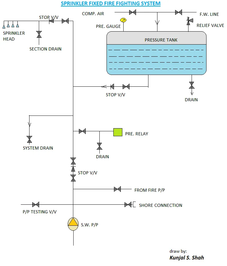
When the surveyor asks "explain the sprinkler fixed fire-fighting system?", start with principle and application: the sprinkler system works on the principle of cooling. It is required on cargo ships of 2000 GT and above and in category-A machinery spaces of 500 m³ in volume and above, which require an additional fixed fire-fighting system.
Power and water supply must be duplicated: the system must have at least two sources of power for the sea-water pump, the alarm and detection system and the fresh-water pump, so that loss of one source does not disable detection, alarm or water supply.
Operating temperature and construction:
- Operating temperature: in accommodation and service spaces heads come into operation within 69 °C to 79 °C; where high temperatures may be expected the operating temperature may be increased by not more than 30 °C above the maximum deckhead temperature.
- Material: sprinkler heads shall be resistant to corrosion by the marine atmosphere.
- Section size: the system is divided into sections and each section is permitted to contain not more than 200 heads.
- Isolation: each section shall be capable of being isolated by one stop valve.
Coverage and hydraulics:
- Coverage: each head covers about 16 m².
- Spacing: heads are spaced not more than 4 m apart and 2 m from the vertical wall.
- Discharge: each head is capable of 100 litre/min discharge.
- Pressure: at the highest sprinkler head the pressure is not less than 4.8 bar.
Fittings every section must have:
- Stop valve located outside the associated section or in a cabinet, clearly and permanently indicated.
- Test valve for testing the automatic alarm for each section by a discharge of water equivalent to the operation of one sprinkler; the test valve for each section is situated near the stop valve for that section.
- Pressure gauge indicating the pressure in the system at each section stop valve and at a central station.
- Connection from the ship's fire main by way of a lockable screw-down non-return valve at the connection, which prevents backflow from the sprinkler system to the fire main — this is the Q22b "can we use the fire pump?" answer: yes, through the NR connection, with no return flow.
- List or zone plan displayed at each indicating unit showing the spaces covered and the location of the zone in respect of each section, with suitable instructions for testing and maintenance available.
Excluded spaces and the paint locker:
- Sprinklers are not fitted where there is no risk of fire, such as void spaces, CO2 rooms and public toilets.
- The paint locker has sprinkler coverage designed at 5 litre/m²/min connected to the fire main pump of the ship.
For "give me the sprinkler figures", answer: 2000 GT, 500 m³, two power sources, 69–79 °C plus 30 °C, 200 heads per section, 16 m² per head, 4 m spacing, 2 m off the wall, 100 L/min per head, 4.8 bar at the top head, one stop valve per section, test valve equal to one head, gauges per section plus central, 5 L/m²/min paint locker.
Sprinkler section rules & fittings:
Deckhead Spacing Grid
- Each standard sprinkler head covers ~16 m² floor area
- Maximum spacing between adjacent heads is 4.0 meters
- Distance from any vertical bulkhead / wall ≤ 2.0 meters
- Maximum 200 sprinkler heads served by one section valve
Section Hydraulic Limits
- Continuous delivery of 100 L/min per activated head
- Pressure at highest deckhead sprinkler head ≥ 4.8 bar
- Dual power sources for seawater replenishment pump
- Pressure tank maintains air/water cushion continuously
Fittings & Exclusions
- Section stop valve lockable outside protected space
- Test valve discharge equivalent to 1 operating head
- Lockable screw-down NR valve prevents fire main backflow
- No sprinklers in void spaces, CO2 room, or toilets
- Paint locker: 5 L/m²/min connected to fire main
2. Bulb Colours, Head Sketch & Working Range
For "draw the sprinkler head, give its working range, and which liquid is inside the bulb?" (Q22c), give the five colour ratings fluently and describe the sketch without inventing a liquid name beyond the rated temperatures given in the notes:
3. Full Sprinkler Test Procedure (9 Steps)
For "show me the sprinkler test", run the full sequence in order. Every alarm below is indicated on the navigation bridge, the engine room and the fire control room, and the alarm also indicates the particular zone from which it has risen:
-
1Isolate and Prove Zone Isolation: Close the section isolating stop valve; this immediately raises a tamper/isolation alarm indicating zone isolation across all control stations.
-
2Prove the Non-Return (NR) Valve: Open the test valve (calibrated to one sprinkler head orifice); if no water comes out it proves the NR valve placed after the section-isolating valve is seating tight and not leaking.
-
3Drop Section Pressure: Since the section downstream of the NR valve remains pressurised, opening the inspector drain valve causes the water pressure in the section line to decrease rapidly.
-
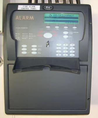
4Prove the Pressure-Switch Alarm: A pressure-switch sensor senses the decreased pressure and raises an alarm at bridge, engine room, and fire station with the zone identifier.
-
5Restore the Section Line: Close the drain valve and reopen the section isolating stop valve to recharge the line.
-
6Prove the Water-Flow Switch: Open the flow test switch/valve to activate an alarm and confirm the paddle/vane flow switch signals continuous water movement.
-
7Confirm All 3 Alarm Locations & Zones: Verify all alarms above are visually and audibly indicated on the navigation bridge, engine room and fire control room, with the correct zone displayed for each.
-
8Close Up, Purge and Repressurise: If all alarm conditions are satisfied, close all testing valves, lock open the section-isolating valve, purge the sprinkler line by air and keep the line fully pressurised.
-
9Verify on Local & Central Gauges: Check from the pressure gauges that proper working pressure (min 4.8 bar at uppermost head) has been restored and maintained.
Recite: isolate → NR check → drain → pressure alarm → restore → flow alarm → bridge + ER + control-room zones → air-purge and repressurise → gauge check.
4. Sprinkler Maintenance Routine
For "how do you maintain the sprinkler system?", list the six routine items plus the drain interval:
Pressure-Tank Level & Recharge
Keep the hydro-pneumatic tank at its marked level (1/3 air, 2/3 fresh water). Recharge air cushion via ship's service compressor and water via top-up pump.
Valve Greasing & Freedom
Grease stems and verify smooth spindle movement for section stop, test, drain, and non-return check valves. Ensure locking chains and padlocks are intact.
Tri-Station Alarm Testing
Prove section tamper switches, line pressure switches, and flow switches signal correctly to Navigation Bridge, Engine Room, and Fire Control Station.
Sea-Water Pump Duty Run
Test automatic cut-in of the dedicated seawater sprinkler pump by closing the isolating valve or bleeding test line to simulate pressure loss.
Pressure-Switch Circuit Blowdown
Drain and blow clear the sensing impulse line so scale and sediment do not block the differential pressure sensor.
Full System Flush & Drain
Perform complete system flush and drain yearly or every 6 months to prevent marine bio-growth and sediment accumulation in dead legs.
Drain the whole system yearly or every 6 months, with tank, valve, alarm and pump checks between drains per the zone-plan instructions.
5. Hypermist Regulation & Protected Spaces
The hypermist (local-application water-mist) fixed system works on the principle of cooling. It is the "other fixed system in the engine room" (Q23):
Release Modes
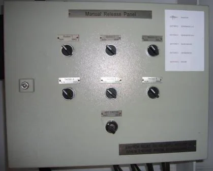
Periodically Unattended (UMS): Both automatic (via dual coincidence detectors) and manual release.
Continuously Manned: Manual release only, to prevent unexpected drenching of watchkeepers.
Protected High-Risk Equipment
Direct targeted protection around: Main Engine cylinder tops & fuel manifolds, Auxiliary Diesel Generators, Auxiliary Boiler fronts/burners, Purifier room separators, and Incinerator burners.
Life Safety & Evacuation
Unlike CO2, hypermist does not displace oxygen across the entire space. It cools the flame zone and knocks down radiated heat without personnel evacuation or shutting ventilation fans.
Oral-exam line — hypermist in four points:
- 2000 GT, 500 m³, cooling.
- UMS: auto plus manual. Manned: manual only.
- Protects M/E, A/E, boiler, purifier, incinerator with no shutdown.
- Visual plus audible alarm on firing.
6. Hypermist Working Chain, Pump & Safeties
For "how does hypermist activate and what are its safeties?" (Q23b, Q23c), trace the signal from detectors to mist:
Two-Detector Coincidence Logic
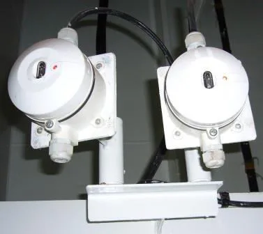
System triggers only when two independent detectors in the same zone activate simultaneously (e.g. Flame + Thermal). This eliminates costly false releases over live high-voltage machinery.
High-Pressure Plunger Pump Unit
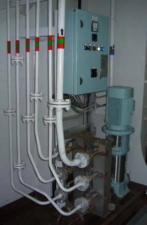
Triplex plunger reciprocating pump delivering 200 L/min at 70 bar. Equipped with suction strainer, unloader relief bypass valve, and pneumatic pulsation dampener.
Venturi Diffuser Mist Nozzle
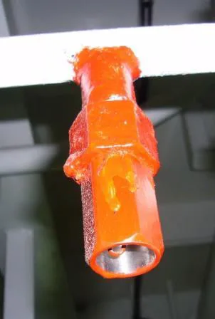
High velocity drop across the nozzle orifice atomizes water into micro-droplets (< 50 μm). Huge surface area extracts 2.26 MJ/kg latent heat and creates localised steam blanket.
Monitored System Safeties
High & low water level switches on break tank, pump discharge overpressure relief valve, suction pressure switch, and supervised line solenoid valves.
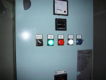
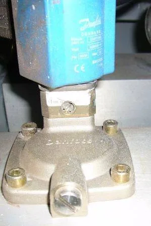
Two detectors → fire panel → hypermist panel → plunger pump 200 L/min at 70 bar → nozzles 12–20 L/min at 50 bar → diffuser mist, guarded by hi-lo water alarm plus two sensors.
7. Oral-Exam Recap & Surveyor Traps
Close the viva by answering Q22 and Q23 back to back in one flow — regulation first, figures second, test and working last:
Q22 sprinkler rapid answers:
- Principle: cooling; 2000 GT and 500 m³ category-A application with two power sources.
- Head rules: 69–79 °C standard, +30 °C hot spaces; corrosion-resistant; 200 heads per isolable section.
- Geometry and hydraulics: 16 m², 4 m, 2 m, 100 L/min, 4.8 bar at the top head.
- Valves and gauges: one stop valve outside or in a cabinet, test valve of one-head equivalent near the stop valve, gauges per section and central.
- Fire-main link: lockable screw-down non-return valve stopping backflow to the fire main; zone plan plus test and maintenance instructions at each indicating unit.
- Exclusions: none in voids, CO2 rooms and public toilets; paint locker at 5 L/m²/min off the fire main.
Q23 hypermist rapid answers:
- Principle: cooling; 2000 GT and 500 m³; UMS auto plus manual, manned manual only.
- Coverage: M/E, A/E, boiler platform, purifier room and incinerator with no shutdown, evacuation or sealing, plus visual and audible alarm.
- Firing chain: two detectors → fire panel zone → hypermist panel → plunger pump and zone solenoid valve.
- Duties: pump 200 L/min at 70 bar; nozzles 12–20 L/min at 50 bar; diffuser throat-drop mist.
- Safeties: hi-lo water alarm switch plus two detector sensors.
| Parameter | Automatic Sprinkler System | Local Application (Hypermist) |
|---|---|---|
| Primary Principle | Cooling via bulk droplet spray | Cooling mist + steam expansion |
| Mandatory Scope | Accommodation, service spaces, control stations | Machinery Cat-A ≥ 500 m³ on ships ≥ 2000 GT |
| Trigger Mechanism | Thermal quartzoid glass bulb (68 °C standard) | Dual coincidence detectors (optical + heat) |
| Discharge Pressure | Min 4.8 bar at the highest head | 70 bar pump discharge; 50 bar at nozzle |
| Delivery Rate | 100 L/min per head over 16 m² | 12–20 L/min per nozzle (fine micro-mist) |
| Machinery Status | Space evacuation not strictly required | Zero shutdown — engines run continuously |
| Water Source | Hydro-pneumatic tank (2/3 FW) + auto S/W pump | Dedicated FW break tank (potable / distilled) |
"Can we use the fire pump?" — yes, through the lockable screw-down NR valve with no backflow. "Where do alarms show?" — bridge, engine room and fire control room with the zone.