Back to Fire Safety
Safety

Deck Foam & Inert Gas (IG) Systems on Tankers

Foam blanket types and deck-foam rates plus inert gas — flammability limits, scrubber, blowers, deck seal and working flow.

12 min read
Advanced
Safety
Key Principles at a Glance 7 points
  • Foam is an aggregate of air-filled bubbles from aqueous solution, lower in density than the lightest flammable liquid, forming a coherent floating blanket that excludes air, cools fuel, suppresses vapour against re-ignition, adheres to surfaces and fills cavities — but foam solutions conduct electricity and are not for electrical fires.
  • Foam concentrates are protein at 3–6% for crude oil, fluoroprotein at 3–6% with a vapour-sealing film for crude or refined oils, special alcohol-type with an insoluble barrier for chemicals, and synthetic AFFF plus medium/high-expansion at 20:1 to 1000:1 for local and engine-room use.
  • SOLAS requires fixed deck foam on ships carrying chemicals or oils in bulk, larger on IMO type-2 and type-3 chemical tankers: oil 0.6 L/m²/min over the whole deck or 6.0 over the largest tank, chemical 2.0 over the whole deck or 20.0 over the largest tank.
  • The deck-foam plant is water supply plus foam-liquid storage with vent, gauge and manhole, automatic 3–6% proportioner fed 10 m head above water pressure by an electric pump, deck main with isolating valves, monitors on normally-closed butterfly valves and four 400 L/min branches.
  • Gas mixtures burn only between LFL (leanest) and UFL (richest): below LFL too lean and above UFL too rich will not burn; higher temperature lowers LFL and raises UFL while greater pressure raises both.
  • Flue-gas IG is scrubbed boiler uptake gas at 4–5% oxygen; tanks are held inert at 8% oxygen or less under 100 mmwg positive pressure, with blowers at 125% plus standby, GRP scrubber with venturi/filter/spray, epoxy P/V breaker, PLC touchscreen in the CCR and O2 analyser venting above 8%.
  • Working flow runs uptake valve → scrubber → overboard/bilge drains → demister → blowers → O2 analyser → deck seal → tanks with P/V valves; theory allows 11.5% oxygen but practice holds 8%; gas freeing replaces IG with fresh air while purging introduces IG to cut O2 and HC; replacement is by dilution or displacement.

1. Foam Principle & Blanket Action

For "explain deck foam for fire fighting?" (Q25), start with what foam is and what the blanket does. Foam for fire protection is an aggregate of air-filled bubbles formed from aqueous solutions, and is lower in density than the lightest flammable liquids.

< Fuel Density Floating Coherent Blanket
4-Way Action Smother, Cool, Seal, Shield
Vapour Seal Stops Re-Ignition
Conductive Never on Electrical Fires

1. Air Exclusion & Smothering

Forms a coherent floating blanket over burning hydrocarbons, creating a physical barrier that cuts off atmospheric oxygen supply to the flame front.

2. Fuel Cooling & Steam Quenching

The water content draining from the bubble matrix cools the liquid fuel below its flashpoint; vaporised drainage water expands into steam to displace oxygen locally.

3. Vapour Suppression & Re-Ignition Barrier

The stable blanket traps volatile hydrocarbon gases beneath the foam surface, preventing flammable vapour from mixing with air even after the fire is out.

4. Surface Adherence & Progressive Attack

Adheres to hot vertical tank bulkheads and pipework, providing radiant heat shielding and allowing firefighters to advance foam coverage progressively across the deck.

Electrical Fire Warning

Because foam solutions consist of salt or fresh water with electrolyte concentrate additives, foam is electrically conductive and strictly prohibited for use on energized switchboards or electrical machinery.

MECHANICS OF THE FOAM BLANKET: AIR EXCLUSION, VAPOUR SEAL & HEAT QUENCHING STEEL BULKHEAD BURNING LIQUID FUEL (CRUDE / HEAVY FUEL OIL) Specific Gravity: 0.82 – 0.95 • Flashpoint ≥ 60 °C ← Aqueous Surfactant Drainage Film AIR-FILLED BUBBLE BLANKET (SG < 0.1) Flames Smothered Trapped Vapours O² Ingress Blocked HOW FOAM EXTINGUISHES 1 Smothers Fire Excludes oxygen from fuel surface. 2 Cools the Fuel Drainage water absorbs sensible heat. 3 Seals Vapours Prevents hydrocarbon re-ignition. 4 Shields Radiant Heat Adheres to adjacent hot bulkheads. CRITICAL SAFETY LIMITATION: Foam solutions contain water and electrolytes — ELECTRICALLY CONDUCTIVE — NEVER APPLY TO LIVE ELECTRICAL EQUIPMENT!
Figure 1: Foam blanket suppression mechanics. The lightweight bubble matrix (specific gravity < 0.1) floats continuously over crude or fuel oil. An aqueous drainage film spreads across the fuel surface, cutting off atmospheric oxygen, cooling the liquid interface, and locking volatile hydrocarbon vapours beneath an airtight barrier to prevent re-ignition.

2. Foam Concentrate Types

The principal use of foam is to extinguish burning flammable or combustible liquid spills or tank fires by developing a coherent coolant blanket. Give the four concentrate families with dilution and duty:

PROTEIN — FILM — ALCOHOL PROTEIN oil fires FILM spreads fast ALCOHOL polar fuels
3% to 6% Standard Dilution Ratio
20:1 – 1000:1 Hi-Ex Expansion Ratio
4 Types Protein, Fluoro, AR, AFFF
+10 m Head Pump Pressure Over Water

Protein Foam Concentrate

Formulated from natural animal protein hydrolysate. Mixed at 3% to 6% with sea/fresh water. Produces a stiff, dense, cohesive blanket with exceptional burnback resistance. Used primarily on crude oil tank fires.

Fluoroprotein Foam Concentrate

Enhanced with synthetic fluorochemical surfactants. Mixed at 3% to 6%. Deposits an ultra-thin vaporisation-preventing film over the fuel surface, resisting fuel contamination and shed fuel pickup. Used on crude oil and refined petroleum products.

Alcohol-Resistant (AR) Concentrate

Contains hydrophilic polysaccharide polymers. When applied to water-miscible polar solvents (alcohols, ketones, esters), it precipitates an insoluble polymeric membrane barrier that stops chemical breakdown of the bubble wall. Mandatory for chemical tankers.

Synthetic AFFF & High-Expansion

Aqueous Film Forming Foam (AFFF) spreads rapidly across fuel spills for rapid flame knockdown. High-expansion foam generators produce expansion ratios from 20:1 up to 1000:1, designed for total volumetric flooding of engine rooms and pump rooms.

One-line definitions for oral exam

Protein = crude at 3–6% • Fluoroprotein = film on crude and refined at 3–6% • Alcohol-type = insoluble barrier for chemicals • Synthetic = AFFF, hi-ex 20:1–1000:1 for local and engine-room use.

3. Deck Foam Regulation, Rates & Components

SOLAS/IMO regulation: for ships carrying chemicals or oils in bulk, a fixed deck-foam system for extinguishing fires on deck or in tanks is required. The systems are identical in principle, but for chemical tankers of IMO type 2 and 3 the foam system is considerably larger than for crude-oil tankers, due to the higher fire risk of chemicals.

BLANKET STOPS THE VAPOUR DECK tankers fitted BLANKET seal + cool THROW monitor jets
0.6 L/m²/min Oil Tanker: Whole Deck
6.0 L/m²/min Oil Tanker: Largest Tank
2.0 L/m²/min Chemical: Whole Deck
20.0 L/m²/min Chemical: Largest Tank

System description (components):

1. Water Supply

Dedicated sea-water supply provided by the ship's fire pumps, delivering pressurized water continuously to the foam proportioning station.

2. Foam-Liquid Storage Tank

Stainless steel or epoxy-lined atmospheric tank complete with air vent, level sight glass, pressure vacuum valve, and access manhole.

3. Proportioning Device & Pump

High-pressure electric positive-displacement pump delivering concentrate to the automatic balanced proportioner at 3% to 6%, maintaining a minimum 10 m head pressure above inlet water pressure under all flow conditions.

4. Deck Monitors & Handlines

Deck main equipped with sectional isolating valves. Deck foam monitors isolated by normally-closed butterfly valves, plus four portable foam branchpipes (each 400 L/min solution rate).

Rate memory hook for viva

Oil 0.6 / 6.0 — chemical roughly three times richer at 2.0 / 20.0. Always quote whole-deck first, largest-tank second; proportioner 3–6% with 10 m head margin.

4. Inert Gas: Flammable Limits & Definitions

For "explain the IG system?" (Q26), start with flammable limits, the Coward flammability relationship, and board operational definitions:

0% – 1% HC Too Lean (< LFL)
1% – 10% HC Flammable Envelope (In Air)
> 10% HC Too Rich (> UFL)
≤ 8% O² SOLAS Inert Target (11.5% Critical)

Lower Flammable Limit (LFL)

The leanest combustible mixture capable of propagating flame. For petroleum hydrocarbon vapors in air, LFL is approximately 1.0% by volume. Below LFL, the mixture has insufficient fuel to burn (too lean).

Upper Flammable Limit (UFL)

The richest combustible mixture capable of propagating flame. For petroleum vapors in air, UFL is approximately 10.0% – 11.0% by volume. Above UFL, there is insufficient oxygen to sustain combustion (too rich).

Temperature & Pressure Influence

Rising temperature widens the flammable band (lowers LFL and raises UFL). Higher absolute pressure increases both LFL and UFL, expanding the explosive envelope under compression.

Purging vs. Gas Freeing

Purging: introducing IG into an inert tank to reduce hydrocarbon concentration to ≤ 2% before air admission, preventing entry into the flammable zone. Gas freeing: replacing inert gas with breathable fresh air (21% O²).
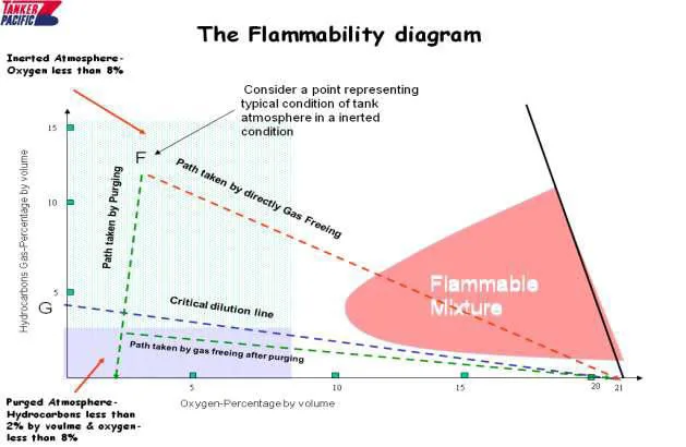
COWARD FLAMMABILITY DIAGRAM: HYDROCARBON – OXYGEN RELATIONSHIP & SAFE PURGING PATH SOLAS SAFE INERT REGIME: O² ≤ 8.0% (COMBUSTION IMPOSSIBLE) FLAMMABLE ENVELOPE (Explosion Risk in Presence of Ignition) LFL 1% UFL 10.5% Critical O² Level = 11.5% Vol SOLAS Max Deck O² = 8.0% Vol × DIRECT AIR DILUTION: CROSSES EXPLOSIVE ENVELOPE (DISASTER) ✓ STEP 1: PURGE WITH IG (HC drops < 2%) ✓ STEP 2: GAS FREE WITH AIR 21% 15% 11.5% 8.0% 5.0% 0% OXYGEN CONCENTRATION (% VOL) → 0% 1% 2% 5% 10% 14% HYDROCARBON GAS CONCENTRATION (% VOL IN AIR/INERT) → KEY SURVEYOR TAKEAWAYS 1. Flammable Boundaries • Below LFL (~1%): Too lean to burn • Above UFL (~10%): Too rich to burn 2. The 11.5% vs 8% Margin • Critical O² limit: 11.5% in theory • Held ≤ 8% for sensor & mix margin 3. Temperature & Pressure • ↑ Temp: widens zone (lower LFL, ↑ UFL) • ↑ Press: raises both LFL and UFL 4. The Purge Golden Rule Never gas-free an over-rich tank with air directly — always purge with IG first!
Figure 2: Coward Flammability Diagram for hydrocarbon vapor and air/inert mixtures. The central shaded envelope defines the explosive zone bounded by LFL (~1% HC) and UFL (~10.5% HC) at atmospheric oxygen (21%), converging at the Critical Oxygen apex (11.5% O²). Tanks are maintained strictly within the green safe zone (≤ 8% O²). Direct air dilution of an over-rich tank (red dashed trajectory) cuts through the explosive envelope, whereas inert gas purging followed by aeration (green trajectory) bypasses flammability entirely.
Hand-drawn flammability diagram — purging vs dilution paths to the safe zone
Reference sketch (course notes): the flammability diagram — purging vs dilution paths to the safe zone. Source: Kunjal Shah Part 2 — Fire Fighting Appliances.
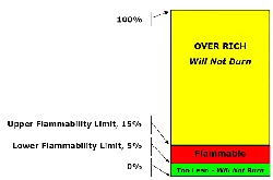
Hand-drawn flammable bands — over-rich, flammable, too-lean — between LFL and UFL
Reference sketch (course notes): the bands — over-rich, flammable, too-lean — between LFL and UFL. Source: Kunjal Shah Part 2 — Fire Fighting Appliances.
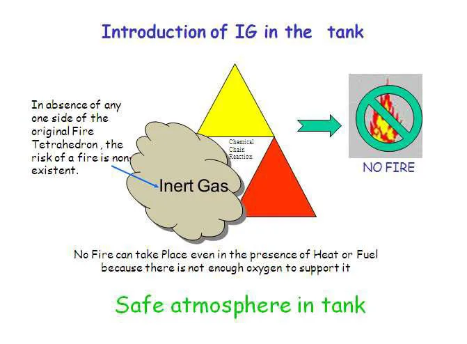
Hand-drawn fire triangle logic — take away oxygen and even heat plus fuel cannot burn
Reference sketch (course notes): the triangle logic — take away oxygen and even heat plus fuel cannot burn. Source: Kunjal Shah Part 2 — Fire Fighting Appliances.
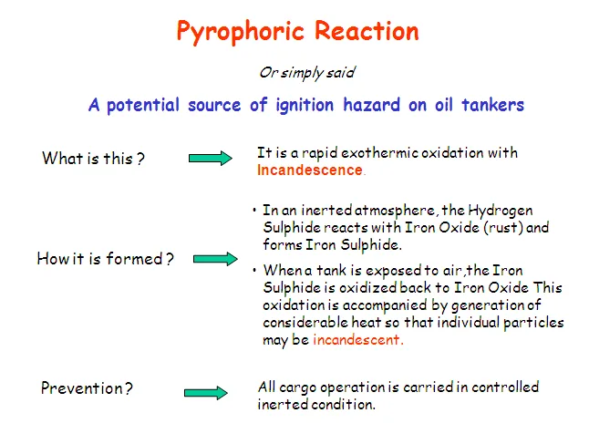
Hand-drawn pyrophoric hazard note — what it is, how it forms, prevention
Reference sketch (course notes): the pyrophoric hazard — what it is, how it forms, prevention. Source: Kunjal Shah Part 2 — Fire Fighting Appliances.

5. IG Plant Construction Parts

Surveyors expect the major plant assemblies to be recited in the exact sequence the gas encounters them from uptake to weather deck:

125% Blower Output vs Pump Rate
> 90% SO² Scrubber Acid Extraction
+100 mmwg Deck Positive Pressure
Low Level Only Active Seal Sensor

1. Boiler Uptake Valve

Controls hot gas take-off from boiler exhaust. Manufactured from heat-resistant cast steel. Fitted with compressed-air sealing to prevent exhaust gas entering the idle plant, plus steam/air soot blowers to clear carbon fouling.

2. Flue Gas Scrubber Tower

Three-stage cooling and cleaning tower internally lined with acid-resistant GRP (glass-reinforced plastic). Features a venturi quencher, impingement wet filter plates, and sea-water spray nozzles. Strips > 90% of SO² and soot, draining effluent overboard via an acidic U-seal.

3. Centrifugal IG Blowers

Two single-stage centrifugal blowers (1 duty + 1 standby) on resilient anti-vibration mountings. Minimum aggregate capacity is 125% of the ship's maximum cargo discharge rate, ensuring positive line pressure under peak discharge.

4. Continuous O² Analyser

Dual paramagnetic or zirconium sensor cells sampling gas post-blower. If oxygen content rises above 8% by volume, it instantly triggers an audible/visual alarm, opens the 3-way atmospheric vent valve, and trips the deck main shut-off valve.

5. Deck Water Seal

The principal barrier separating the hazardous cargo tank deck from the non-hazardous machinery space. Liquid column physically blocks hydrocarbon reverse flow. Equipped with a demister pad and a mandatory low-water-level alarm.

6. Liquid P/V Breaker

Epoxy-coated safety breaker located on the weather deck, filled with a water-glycol mixture. Protects cargo tanks against severe over-pressure or deep vacuum in the event of mechanical high-velocity P/V valve failure.
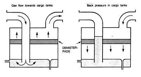
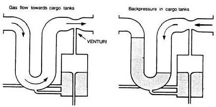
SEMI-DRY DECK WATER SEAL: MECHANICAL CUTAWAY & BACKFLOW REVERSE BARRIER GRP INTERNAL CORROSION LINING IG INLET SEAL WATER RESERVOIR (DEPRESSED BY GAS FLOW) DEMISTER PAD (DROPLET REMOVAL) TO DECK → Seawater Supply Overboard Weir Low-Level Float (Mandatory Alarm) Steam / Electric Heating Coil (Anti-Freeze) STATE 1: FORWARD FLOW — MINIMAL WATER CARRYOVER STATE 2: BACKPRESSURE / REVERSE FLOW SEAL COLUMN RISES Toxic / HC Vapour Reverse Flow Blocked! SOLAS DECK SEAL FAMILIES: Wet Type: Bubbles constantly through water; prone to droplet carryover into cargo. Semi-Dry (Shown): Uses venturi; water drawn into column only on backpressure. Dry Type: Automated drop valves; zero carryover but fails dangerous if valves stick.
Figure 3: Semi-dry deck water seal mechanical engineering cutaway. In normal forward flow, gas pressure depresses the water bed through a venturi orifice, passing through a multi-layer wire mesh demister to the deck without bubbling violently. On plant shutdown or cargo tank backpressure, the water column instantly rises up the inlet pipe, creating an impermeable hydrostatic liquid lock that isolates toxic and flammable hydrocarbon vapors from machinery spaces.
Hand-drawn deck seal under flow vs back-pressure — demister pads and water lock
Reference sketch (course notes): the deck seal under flow vs back-pressure — demister pads and water lock. Source: Kunjal Shah Part 2 — Fire Fighting Appliances.
Hand-drawn venturi seal variant
Reference sketch (course notes): the venturi seal variant. Source: Kunjal Shah Part 2 — Fire Fighting Appliances.
Hand-drawn drop-tank seal with its automatic valve
Reference sketch (course notes): the drop-tank seal with its automatic valve. Source: Kunjal Shah Part 2 — Fire Fighting Appliances.

6. IG Working Flow, Oxygen & Gas Replacement

For "trace the inert gas from boiler uptake to cargo tank", explain the process as ordered engineering stages with operational parameters:

EXHAUST BECOMES SHIELD CLEAN scrub + cool THIN O2 under 8 pc HOLD pressure + seal
1
Boiler Uptake Gas Extraction: Exhaust gas containing 4% – 5% O² is drawn from the auxiliary boiler uptake via an air-sealed, heat-resistant butterfly valve fitted with automated soot blowers.
2
Quenching & Washing in Scrubber: Flue gas enters the GRP-lined scrubber tower where seawater sprays and a venturi throat cool the gas from 350°C down to < 40°C while stripping > 90% of SO² and particulates; acidic effluent drains overboard.
3
Moisture Demisting: Cooled gas passes through a polypropylene mesh demister pad to eliminate liquid water droplet carryover prior to entering the blowers.
4
Blower Pressurisation: Centrifugal blowers (125% aggregate capacity, 1 duty + 1 standby) pressurise the dry inert gas, maintaining positive distribution head along the main.
5
Continuous Oxygen Analysis & Trip: Paramagnetic analysers sample gas quality. If O² exceeds 8.0% by volume, the 3-way atmospheric dump valve trips open and the deck isolating valve trips closed.
6
Deck Water Seal & Mechanical Non-Return: On-specification gas (O² ≤ 5%) flows through the deck water seal, mechanical non-return valve, and manual deck isolation valve onto the tanker weather deck.
7
Tank Distribution & P/V Breaker Protection: Gas enters cargo tanks held at ≥ +100 mmwg positive pressure. A liquid P/V breaker and individual high-velocity P/V valves protect structural integrity against over-pressure or vacuum.

Gas Replacement Principles (Viva Question):

Dilution Method (Turbulent Mixing)

Inert gas is injected at high velocity from deck level, penetrating to the tank bottom. It mixes turbulently with existing vapors, and the homogeneous mixture is continuously expelled from top vents. Requires approximately 3 to 4 tank volumes of IG to achieve safe levels.

Displacement Method (Piston Layering)

Utilises density differences. Cool, dense inert gas enters the tank top at low velocity, settling to the bottom like a piston and lifting the lighter, warmer hydrocarbon vapors upward and out through the bottom purge pipe. Highly efficient, requiring only 1.2 to 1.5 tank volumes.

Exam Recital Sequence

Deliver the process in surveyor cadence: Boiler Uptake → Scrubber → Demister → Blowers (125%) → O² Analyser (Dump > 8%) → Deck Water Seal → Deck Isolating Valve → Cargo Tanks (+100 mmwg) guarded by Liquid P/V Breaker.

7. Foam & IG Oral-Exam Recap

Surveyors frequently pair fixed deck foam (Q25) and inert gas systems (Q26) in a single high-intensity oral exam segment. Master the exact operational numbers and system schematics below:

Vessel / System Whole Deck Rate Largest Tank Rate Regulatory Basis
Oil Tanker Deck Foam 0.6 L/m²/min 6.0 L/m²/min SOLAS II-2 Reg 10.8 • 20 min discharge
Chemical Tanker Deck Foam 2.0 L/m²/min 20.0 L/m²/min IBC Code Chapter 11 • Alcohol-resistant foam
Foam Proportioner Pump +10 m head (~1.0 bar) above water inlet pressure Positive displacement • 3% to 6% automatic
Inert Gas Oxygen Level ≤ 5% O² at Blower ≤ 8% O² in Cargo Tanks SOLAS II-2 Reg 4.5.5 • 11.5% theoretical stop
Fixed IG Carriage (from 1 Jan 2016) All tankers ≥ 8,000 DWT (previously ≥ 20,000 DWT) SOLAS II-2 Reg 4.5.5 as amended
DECK FOAM BALANCED PRESSURE PROPORTIONING SYSTEM & WEATHER DECK STATIONS SEAWATER FIRE MAIN Press: 8 – 10 bar from Fire Pumps FOAM STORAGE TANK (3% - 6%) Foam Pump (+10m Head Margin) BALANCED PROPORTIONER Diaphragm Sensing FOAM SOLUTION MAIN → Section Valve N.C. Butterfly DECK MONITOR Aspirating Nozzle Branchpipe (400 L/min) SOLAS REQUIREMENT: Fixed deck monitors cover all cargo tanks plus 4 portable foam branches (400 L/min each) for spill control.
Figure 4: Deck foam balanced pressure proportioning P&ID. A positive displacement foam pump delivers concentrate at +10 m head above fire main seawater pressure. The diaphragm-actuated proportioner meters concentrate at 3% to 6% into the solution main, supplying weather deck monitors isolated by normally-closed butterfly valves, alongside 400 L/min portable handline branchpipes.
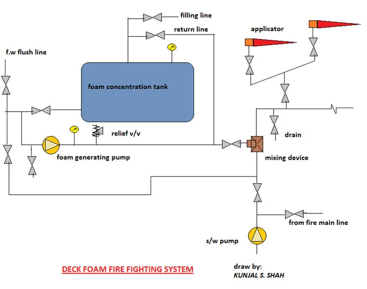
Hand-drawn deck foam system — concentrate tank, pump, mixing device and applicators
Reference sketch (course notes): the deck foam system on one page — concentrate tank, pump, mixing device and applicators. Source: Kunjal Shah Part 2 — Fire Fighting Appliances.
FULL PROCESS P&ID: BOILER FLUE-GAS INERT GAS SYSTEM FROM UPTAKE TO CARGO TANKS BOILER UPTAKE 4 – 5% O² 350 °C Uptake Damper (Air Sealed) SCRUBBER TOWER (GRP) DEMISTER SW Spray Acidic Drain o/b Blower 1 (125%) Blower 2 (Standby) O² ANALYSER Paramagnetic Atm Vent (O²>8%) DECK WATER SEAL Low-Level Trip Deck NRV Deck Main Valve WEATHER DECK MAIN LIQUID P/V BREAKER TK 1 ≤8% O² TK 2 ≤8% O² POS. PRESSURE ≥ +100 mmwg SOLAS IG FAIL-SAFE SEQUENCE: Uptake Valve → Scrubber → Blowers → O² Analyser (>8% Vents to Atmosphere) → Deck Water Seal → Tanks Double block and bleed protection stops hydrocarbon backflow into the engine room; liquid P/V breaker prevents hull rupture or implosion.
Figure 5: Complete process P&ID of a marine flue-gas inert gas installation. Hot boiler exhaust gas (350°C, 4–5% O²) is quenched and washed in a GRP scrubber tower, dried through an impingement demister, pressurised by 125% centrifugal fans, monitored continuously for oxygen content (>8% trips the atmospheric dump valve), and delivered through the semi-dry deck water seal to cargo tanks maintained at positive pressure (≥ +100 mmwg) with liquid P/V breaker overpressure and vacuum relief.
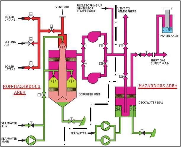
Hand-drawn whole IG plant colour-coded — non-hazardous vs hazardous sides, scrubber, fans and seals
Reference sketch (course notes): the whole IG plant colour-coded — non-hazardous vs hazardous sides, scrubber, fans and seals. Source: Kunjal Shah Part 2 — Fire Fighting Appliances.
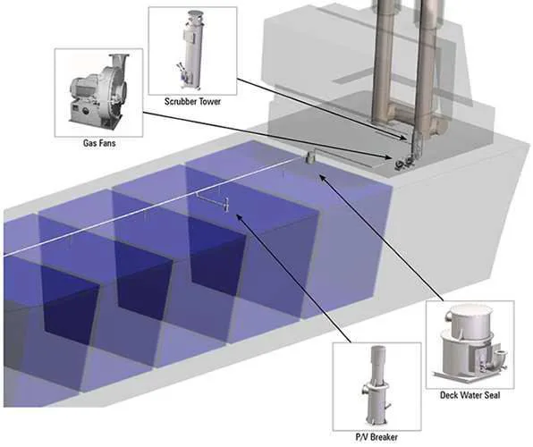
The IG deck in 3D — tower, fans, seal and breaker positions
Reference photo (course notes): the IG deck in 3D — tower, fans, seal and breaker positions. Source: Kunjal Shah Part 2 — Fire Fighting Appliances.
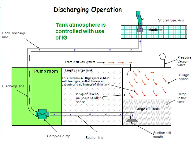
Hand-drawn discharging under IG — ullage, pumps and vapour paths
Reference sketch (course notes): discharging under IG — ullage, pumps and vapour paths. Source: Kunjal Shah Part 2 — Fire Fighting Appliances.
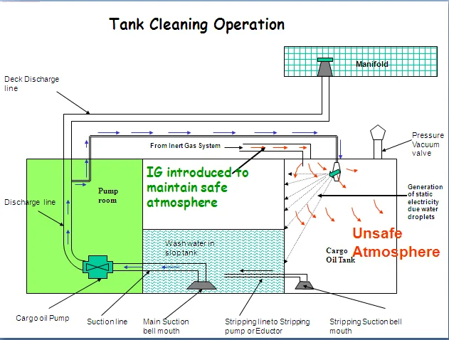
Hand-drawn tank cleaning under IG — unsafe-atmosphere warning zones
Reference sketch (course notes): tank cleaning under IG — note the unsafe-atmosphere warning zones. Source: Kunjal Shah Part 2 — Fire Fighting Appliances.
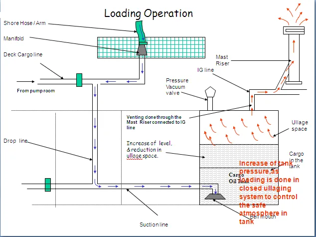
Hand-drawn loading under IG — level rise, pressure and venting paths
Reference sketch (course notes): loading under IG — level rise, pressure and venting paths. Source: Kunjal Shah Part 2 — Fire Fighting Appliances.