
CO2 Fixed Fire-Fighting System on Ships
The CO2 fixed system end to end: bottles and regulations, the CO2 room and safeties, quantity calculation and maintenance, and engine-room and purifier fire actions.
Key Principles at a Glance 6 points
- CO2 extinguishes by smothering plus cooling, bringing oxygen below 15 percent; category-A machinery spaces of 500 cu m and above need a fixed system that puts 85 percent of the charge in within 2 minutes.
- Bottles are drawn steel hydro-tested to 228 bar, stowed below 55 °C at about 52 bar, checked by level, radio-isotope or weighing, each with a syphon tube and a bursting disc set for 177 bar at 63 °C.
- The CO2 room is for sole use, not more than one deck below the open deck with stair or ladder access, 6 air changes per hour, outward-opening gas-tight doors, below 55 °C, 2.4 m headroom — and aft of the collision bulkhead if sited outside machinery spaces.
- System safeties run from the cabinet trip switch through master valve, manifold relief, bottle safety pins, non-return check valve and the 4-bar leak alarm with its cooler-bottle hunt procedure, piped in mild steel galvanised with insulated, ventilated, gas-tight room boundaries.
- Quantities are 30 percent of the largest cargo space, 40 percent of the largest machinery space excluding casing (35 percent including casing), using volume-times-factor over 0.56 (cu m per kg at 21.1 °C and 1 bar) over 45.4 kg per cylinder — the worked vessel needs 212 bottles at 58 bar, 120 kg charge with 72–80 tare, 120 s design against 107 s actual.
- Engine-room fire action is alarm, muster, headcount, ventilation stops, fuel stops, boundary cooling and CO2 release; purifier-room action adds stopping the purifier from outside, shutting purifier ventilation, flaps and fuel QCV, with prevention by double-sheathed pipes, drip trays, anti-spill tape, mist plus CO2, quick-closing valves with remote stops, and detection.
1. Principle, Regulation & CO2 Bottles
This is the most important section in the Safety oral — surveyors ask at least one main question from CO2, and a weak answer here fails the sitting. For "what is the principle of CO2 flooding?" — smothering plus cooling, reducing the oxygen content to below 15 percent so combustion cannot sustain. The system works only inside enclosed spaces — in open space it does not work at all — so it protects machinery spaces, engine rooms, purifier rooms and cargo holds.
- Regulation: SOLAS requires that a ship with a category-A machinery space of 500 cu m and above volume be fitted with an additional fixed fire-fighting system.
- Discharge rule: 85 percent of the required CO2 quantity must be released into the space within 2 minutes of actuating the system — and of evacuating the fire-affected space.
- Operation authority: the system must be operated by the Chief Engineer or Second Engineer — those two are responsible for the whole release operation.
CO2 bottles — construction and fittings:
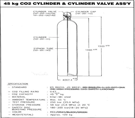
- Bottles are solid drawn steel, hydraulically tested to 228 bar.
- Bottles must not be stored where the temperature exceeds 55 °C; bottle pressure is normally about 52 bar and varies with temperature.
- Contents are checked by level indicator, radio-active isotope gun, or weighing.
- In each bottle head assembly the bursting disc is designed to rupture at 177 bar produced by a temperature of about 63 °C.
- Each bottle has a syphon tube so that liquid CO2 is discharged from the bottle.
Why the syphon tube matters — say this line:
- Without the syphon tube the CO2 would evaporate from the surface, giving a very slow discharge rate and, by taking its latent heat, would cause the remaining CO2 in the bottle to freeze.
- Liquid discharge at the nozzle flashes to gas — that flash gives the cooling half of the principle alongside smothering.
Liquid CO2 sits at the bottom and flashes to gas at the nozzle — that flash gives the cooling half of the principle. A bottle without its dip tube blows vapour only, so always confirm syphon tube + bursting disc 177 bar at 63 °C in one breath.
2. CO2 Room, Safeties & Leak Hunting
For "describe your CO2 room" (Q21c), give the room first, then the safety chain, then the leak drill:
CO2 room regulation (Q21c):
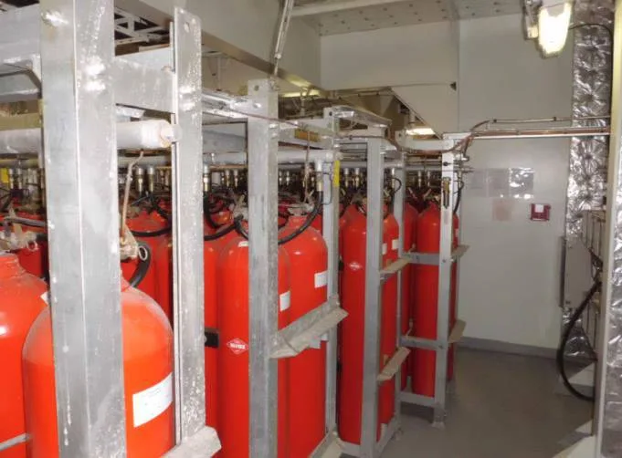
- The storage room shall be used for no other purposes.
- If below deck, it shall be no more than one deck below the open deck and directly accessible by stairway or ladder from the open deck.
- Spaces below deck, or without open-deck access, shall have mechanical ventilation taking exhaust from the bottom of the space, sized for at least 6 air changes per hour.
- Access doors open outwards, and bulkheads, decks, doors and every closing means forming boundaries with adjacent enclosed spaces shall be gas tight.
- Room temperature maintained below 55 °C.
- Minimum clear height 2.4 m for manifold mounting and cylinder weighing.
- If the fixed medium is stored outside a protected space, it shall sit in a room behind (aft of) the forward collision bulkhead.
System safeties (Q21b) — walk the chain in order:
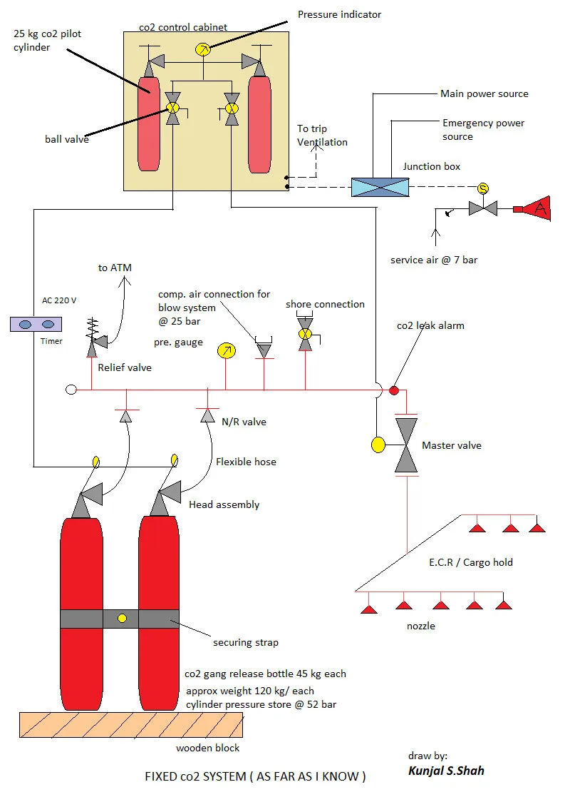
- Trip switch: the control cabinet has a special trip switch for ventilation trip and CO2 alarm — as soon as you open the cabinet it trips ventilation and sounds the alarm.
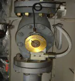
- Master valve (Q21d): fitted on the main manifold line going to machinery or cargo spaces — it prevents CO2 reaching any space on an accidental release; open it only as part of the ordered release sequence.
- Relief valve: located at the end of the manifold — if manifold pressure exceeds the set point it lifts to atmosphere at 180 bar.
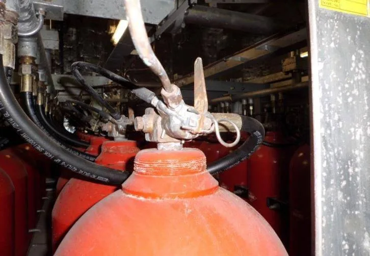
- Safety pin: provided in each bottle head assembly — it locks the operating lever against accidental operation; pull it out for manual operation.
- Bursting disc: also in each bottle head assembly — bursts when bottle pressure exceeds 177 bar with about 63 °C around the bottle.
- Non-return check valve: located between each bottle and the manifold — acts as a non-return so that blow-through service air cannot pass back, and on a partial release (a few bottles for a cargo hold) the pressurised manifold cannot force open the unoperated bottles after the pilot cylinder fires.
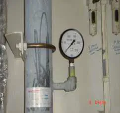
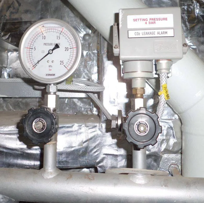
- CO2 leak alarm: located on the manifold, working as a pressure switch at 4 bar. Any leaking bottle feeds gas into the manifold; at 4 bar it trips the alarm. Since even a small leak off a 52-bar bottle pressurises the manifold fast, the alarm tells you a bottle leaks — but never which one. Finding it: two persons go together with communication equipment, ventilate the room and wait outside until gas-free, then enter and hand-touch bottles in turn — the leaking bottle is markedly cooler than its neighbours. Mark every cooler bottle, check all of them, and report the count.
- Pipework: solid drawn mild steel, galvanised against corrosion.
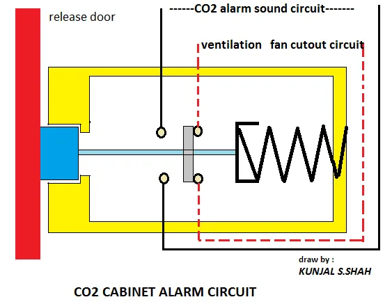
Break glass, unlock remote release cabinet door. The integrated microswitch trips mechanical ventilation fans, closes fire dampers automatically, and activates pre-discharge audio-visual alarms in protected spaces.
Verify all crew members evacuated via headcount. Confirm quick-closing valves (QCV) tripped, fuel pumps stopped, and all skylights/doors sealed gas-tight.
Open the designated master distribution valve to the space requiring extinction (Engine Room or Cargo Hold). This ensures the discharge line to nozzles is open before high-pressure gas is released into the manifold.
Pull the pilot bottle release lever. High-pressure pilot gas travels down the pilot line to pneumatically open the cutter heads across the required cylinder bank, discharging 85% of CO2 within 2 minutes.
3. Quantity Calculation & the Worked Vessel
For "how much CO2 does your ship carry?" (Q21e), give the percentages, the formula, then your ship's worked example:
SOLAS quantity regulations & formulas:
Cargo Holds (30%)
30% Gross Volume Formula:
N = (V_cargo × 0.30) ÷ 0.56 ÷ 45.4
- Sized for the largest single protected cargo hold
- Gas delivered selectively via 3-way distribution manifold
- 0.56 m³/kg is free CO2 volume at 21.1 °C, 1 bar
Machinery Space (40% / 35%)
Casing Area Rule:
Excl: 40% • Incl: 35% ÷ 0.56 ÷ 45.4
- Use 40% if casing area ≤ 40% of horizontal floor area
- Use 35% if casing is included in total volume
- Must discharge ≥ 85% of total required gas in ≤ 2 minutes
Worked Vessel Bank (212 Bottles)
Shipboard Installation:
- 201 Cylinders: Main Engine Room total flood
- 7 Cylinders: Dedicated Purifier Room flood
- 4 Cylinders: Uncommitted spare inventory
- Actual Test: 107 s total discharge (within 120 s design)
- Storage: 58 bar @ 21 °C; tare 72–80 kg; gross ~120 kg
4. Weighing & the Maintenance Schedule
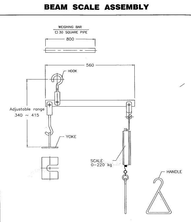
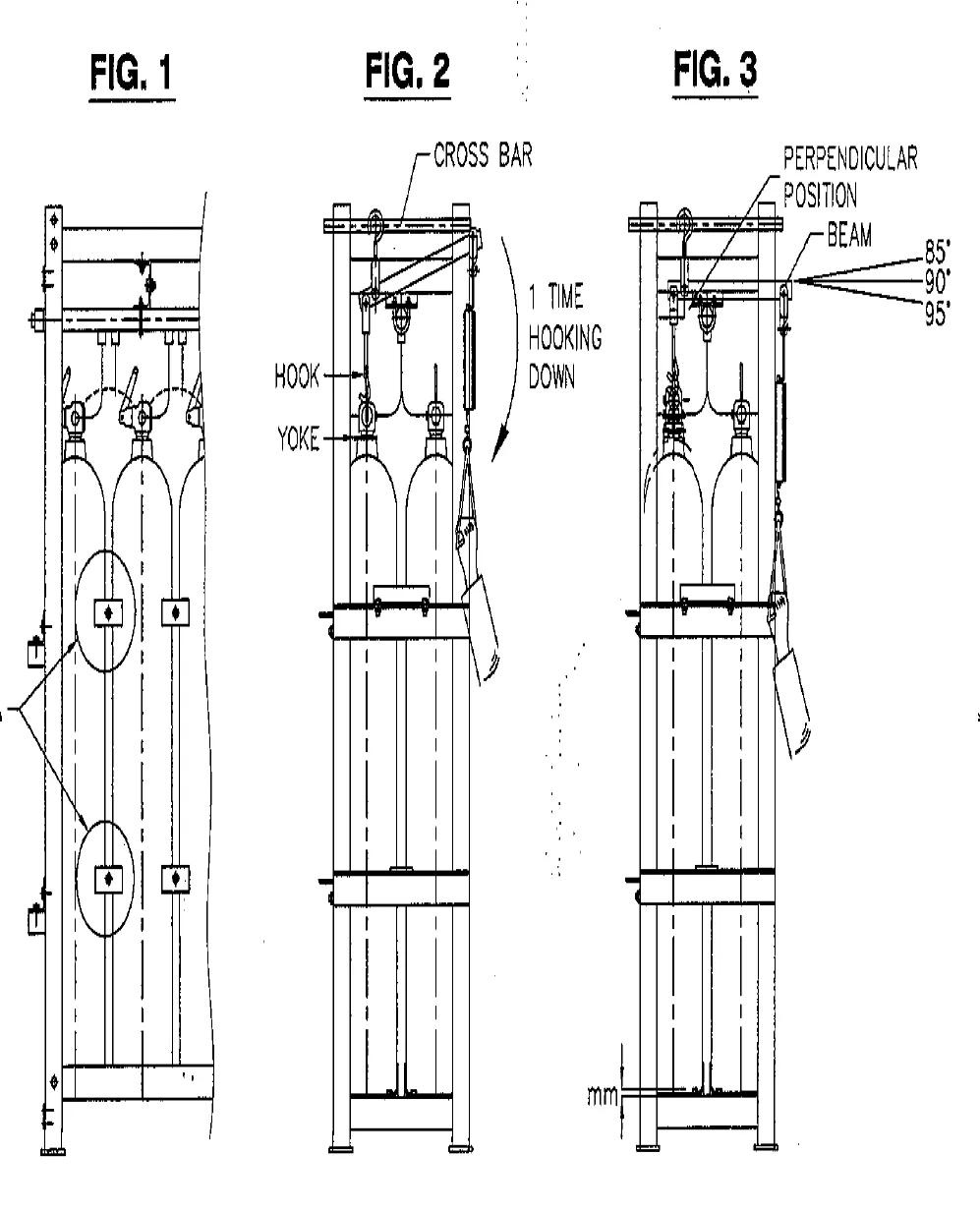
For "how do you weigh a bottle?" (Q21f) and "what maintenance?" (Q21g), give the tool, the steps, then the full interval table:
SOLAS CO2 System Maintenance Ladder:
| Interval | Inspection / Service Action | Test Pressure & Criteria |
|---|---|---|
| Weekly | Room ventilation run, cylinder clamping tightness, mechanical linkage checks, flexible loop hoses inspected. | Bridge notified; 2-person safety buddy system; gas-free check. |
| Monthly | Remote release cabinet door opened; pre-discharge alarm & ventilation trip interlocks verified. | Microswitch trips fans and closes fire dampers automatically. |
| Yearly | Pneumatic through-blow of all manifold piping and distribution lines with service air. | 25 bar compressed service air; ensures nozzles clear of rust/scale. |
| 2-Yearly | 100% cylinder inventory weighed using calibrated mechanical beam-scale or ultrasonic level detector. | Recharge mandatory if content loss > 10% (> 4.54 kg). |
| 5-Yearly | Manifold spring-loaded safety relief valve bench pressure test; internal valve inspection. | 180 bar pop test pressure; seats resealed and class stamped. |
| 10-Yearly | Hydrostatic pressure testing of all seamless high-pressure CO2 cylinders (hydraulic stretch test). | 250 bar hydraulic test; retested every 5 years after the initial 10-year survey. |
| 15-Yearly | Complete distribution pipeline sectional hydraulic pressure testing: manifold to nozzles. | 170 bar (manifold), 80 bar (section master valves), 6–7 bar (nozzles line). |
5. Engine-Room & Purifier-Room Fire Actions
Knowledge of the system is only half the question — the surveyor then gives you a fire: "E/R on fire — your actions?" Note first that the engine room also has a hypermist system — if you are sure it will extinguish the fire you may operate it with no shutdowns needed; but if the surveyor asks for CO2, explain CO2.
Fire in the engine room — actions in order:
- On seeing fire anywhere in the engine room, immediately raise the fire alarm from the nearest point by breaking the glass — and if the hammer is missing, remove a safety shoe and strike with its steel toe plate.
- If the fire type is recognisable and not too big, attack with the proper portable extinguisher.
- If it cannot be extinguished, immediately run to inform the Chief Engineer and the deck officer or bridge — report location and type of fire.
- If the main engine is running, slow down and stop it.
- Before leaving the engine room on orders to release CO2, make sure all accesses are closed properly.
- Stop the running auxiliary engines and start the emergency generator on load — stopping the auxiliaries also stops ventilation; then close the flaps.
- All crew except the bridge watchkeeper (or officer/master) muster for headcount, then follow muster-list duties — closing vents, doors, flaps, dampers and quick-closing fuel valves.
- Start the emergency fire pump for boundary cooling of the engine-room bulkheads, continuously.
- Operate CO2 from the fire control station; confirm every crew member present, nobody missing.
- Open the release cabinet with the key — opening it cuts ventilation power and sounds the CO2 release alarm in the engine room.
- Operate the pilot-cylinder valve and the master valve to release the gas.
- Continue boundary cooling and check the bulkhead temperatures from time to time.
Fire in the purifier room — actions in order:
- The purifier room also has hypermist — use it if it will help, with no shutdowns; explain CO2 when the surveyor asks for CO2.
- Immediately raise the fire alarm by breaking the glass (shoe-steel-toe fall-back as above).
- Stop the purifier from outside the room with the emergency stop.
- If the fire type is recognisable and not too big, use the proper portable extinguisher.
- Close the purifier-room door — do not forget to close it.
- Immediately run to inform the Chief Engineer and the deck officer or bridge — location and type of fire.
- Shut purifier-room ventilation from the MSB and shut the flaps.
- Shut the quick-closing fuel valve for the purifier line only.
- Carry out boundary cooling for the purifier room.
- The Chief Engineer releases CO2 from outside the purifier room or from the fire control station; keep up boundary cooling.
Alarm → muster → headcount → stops → dampers → cooling → evacuate → release. Actions out of order — cooling before stops, release before headcount — fail the question even when every item is named.
6. Purifier Fire Prevention & Closing Drill
The surveyor's last move is "how do you prevent a purifier fire?" — give the six fitted defences, then close with the number drill:
Prevention of purifier fires — six points:
- All pipes leading to the separator are double-sheathed — an inner-pipe leak drains into the outer pipe instead of spraying over the room.
- Drip trays below the purifier/separator catch spilled oil so it cannot flow, spread and touch hot material.
- All pipe flanges and connections are wrapped with anti-spill tape to contain flange leakage.
- Fixed protection fitted: water-mist and CO2 systems installed in the space.
- Quick-closing valves and remote stopping of pumps and purifier provided.
- Fire detection and alarm system provided so quick action can be taken.
Closing number drill — recite cold:
- Principle: smothering + cooling, O2 below 15%; cat-A ≥ 500 cu m; 85% in 2 min.
- Bottles: drawn steel, hydro 228 bar, stow ≤ 55 °C at ~52 bar, disc 177 bar at 63 °C, syphon tube against freezing.
- Room: sole use, ≤ 1 deck down with stair/ladder, 6 changes, outward gas-tight doors, 2.4 m, aft of collision bulkhead.
- Quantities: 30 / 40 / 35% through V × factor / 0.56 / 45.4; ship carries 212 at 58 bar, 107 s vs 120 s.
- Upkeep: beam 0–220 kg ± 5°, recharge at 10%; ladder 25 – weigh – 180 – 250 – 170/80/6-7.
"Why not release CO2 immediately?" — because men, ventilation and fuel come first: evacuate, headcount, stop air and fuel, seal, cool boundaries — then release. CO2 in a breathing, ventilated space kills men and wastes gas.