
Ship Fire Main & Emergency Fire Pump System
The fire main backbone, main and emergency pumps, hoses, nozzles, hydrant pressures and valves — every figure in one place.
Key Principles at a Glance 7 points
- The fire main is the backbone of ship firefighting: sea-water inlet, suction piping, fire pumps and distributed hydrants giving a ready water source at every point, cooling the fire and converting to steam at 1600 times expansion to smother it.
- Water absorbs about 2.6 kJ per gram through heating to 100 °C and conversion to steam, cutting vapour generation at the fuel surface; the steam cloud displaces air around the fire.
- Two main fire pumps are fitted with remote start and sea suction valves kept open; performance is two 12-metre jets, and the system also serves boundary cooling and Class-A fires.
- The emergency fire pump sits outside the machinery space at embarkation-deck level with independent diesel drive, battery plus hand-crank starting and priming, giving 40% of the main capacity with minimums of 25 m³/h and 15 m³/h.
- Fire hoses are synthetic woven textile, rubber-lined and PVC-coated, 18 m long with 64 mm couplings; deployed lengths are 15 m in machinery spaces, 20 m elsewhere and on deck, and 25 m on wide decks over 30 m beam; annual test at 50% over working pressure, 17 bar working and 24 bar test.
- Nozzles are approved dual-purpose jet plus spray with shut-off in 12, 16 and 19 mm with 12 mm in accommodation, at 5 L/m²/min; hydrant pressure with two pumps running is 3.5 kg/cm² at the topmost hydrants with pax 0.40/0.30 and cargo 0.27/0.25 rules.
- Relief valves guard against over-design pressure and shore supply in dry dock, drain valves guard against icing, and screw-down isolating valves outside tenable positions — tankers at the poop front plus 40 m tank-deck intervals — keep the rest of the main alive; main diameter serves two pumps together, 140 m³/h on cargo ships.
1. Fire Main Purpose & General Principles
The fire main is a system consisting of sea-water inlet(s), suction piping, fire pumps and a distributed piping system supplying fire hydrants, hoses and nozzles located throughout the vessel. Its purpose is to provide a readily available source of water to any point throughout the vessel which can be used to combat a fire, and it is considered the backbone of the fire-fighting systems on board.
Through the fire main the firefighter gets a reliable and versatile system offering several methods of attack: water can be supplied as a straight stream (jet) for deep-seated fires, as a spray for combustible-liquid fires where cooling and minimum agitation is desired, or as a means to protect personnel where cooling is the primary effect desired.
Extinguishing capabilities of water:
Sensible & Latent Heat Absorption
Heating water from ambient to 100 °C and converting it into steam absorbs 2.6 kJ/g (1117 BTU/lb). This massive thermal sink drops the combustion zone temperature below the fuel's auto-ignition point.
1600× Smothering Steam Blanket
Upon vaporisation at atmospheric pressure, 1 m³ of liquid water expands into 1600 m³ of steam vapour, rapidly displacing ambient oxygen around the flame envelope and suffocating the combustion.
Versatile Jet & Spray Delivery
Applied as a solid high-velocity jet for deep-seated Class-A embers, a wide-angle mist fog for cooling Class-B oil spills without fuel splashing, and water curtains for boundary cooling of adjacent bulkheads.
Distributed Ring Architecture
Supplied by at least 2 independent main pumps plus 1 emergency fire pump outside machinery spaces, serving distributed deck hydrants equipped with instantaneous couplings and dual-purpose nozzles.
For "what is the purpose of the fire main?", say: backbone of firefighting — sea inlet to hydrants everywhere — cooling plus 1600× steam smothering at 2.6 kJ/g — applied as jet, spray and boundary cooling.
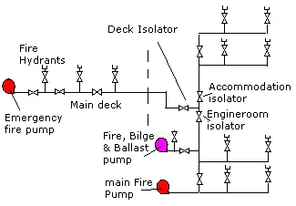
2. Emergency Fire Pump Regulation
Apart from the main fire pumps, an emergency fire pump is provided for emergencies such as CO2 flooding or main fire pumps dysfunctional. For "give the emergency-pump regulation", give position, drive, suction and figures together:
Position & Smoke-Free Access
Located outside the engine room, preferably on the same level as the embarkation deck. Positioned so fire, smoke, or toxic gas in the machinery room cannot block access or contaminate its air supply.
Self-Contained Prime Mover
Independent diesel engine with battery start plus manual hand-cranking or hydraulic/spring starting as the alternate. If electrically driven, power comes exclusively from the emergency switchboard.
Suction & Priming at Lightest Draft
Must draw suction without external support under lightest seagoing draft in any condition of list (15°) and trim (10°). Equipped with dedicated water-ring or compressed-air priming unit.
A-60 Boundary & Pipe Reinforcement
Unit, suction, and electrical cables must not reside in the main pump space. Any suction pipe traversing machinery spaces must have ≥ 11 mm wall thickness, all-welded joints, and A-60 fire insulation.
Recite: 40% — 25 — 15 — 2 × 12 m: 40% of main capacity, 25 or 15 m³/h minimum, throwing two 12-metre jets — from outside the machinery space at embarkation-deck level.
3. Hoses, Nozzles & Hydrant Pressures
Hoses and nozzles carry the water from the hydrant to the fire — surveyors test construction, stowage, lengths, couplings and pressures closely.
Fire Hose Construction & Testing
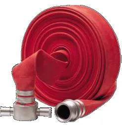
Made from synthetic woven textiles, lined with smooth synthetic rubber and coated with PVC. Highly resistant to rot, mildew, marine climate, and hydrocarbons. Tested annually to 50% above working pressure (17 bar WP → 24 bar TP).
Dual-Purpose Nozzle Function
Approved type incorporating solid jet, wide-angle spray, and complete shut-off in one twist assembly. Orifices: 12 mm, 16 mm, and 19 mm (accommodation restricted strictly to 12 mm). Delivers average ≥ 5 L/m²/min.
Two-Jet Coverage Mandate
Hydrant positions must allow at least two jets of water from separate hydrants (one from a single length of hose) to reach any normally accessible area on board, including cargo spaces when empty.
SOLAS Hydrant Working Pressures
With 2 main pumps running: 3.5 kg/cm² (50 psi) at top two hydrants.
Passenger Ships: ≥4000 GT: 0.40 N/mm² | <4000 GT: 0.30 N/mm²
Cargo Ships: ≥6000 GT: 0.27 N/mm² | <6000 GT: 0.25 N/mm².
4. Relief, Drain & Isolating Valves
Valves keep the main alive when part of the ship is on fire, and protect the pumps and the main itself.
Spring-Loaded Pressure Relief Valve
Fitted on pump discharge headers. Automatically lifts if pumps exceed pipework design pressure. Crucially protects ship pipework and hydrants from excessive pressure during shore supply connection in dry dock.
Low-Point Anti-Freezing Drain Valves
Fitted at all low points along weather deck and exposed fire mains. Drains standing water when the system is idle, preventing catastrophic pipe ruptures caused by water freezing in sub-zero polar latitudes.
Machinery Space Isolating Valve
Fitted in an easily accessible and tenable position outside the engine room. When closed, keeps the entire deck and accommodation fire main pressurised via the emergency pump even if the engine room is flooded or ablaze.
Tanker Poop Front & 40 m Deck Valves
On oil/chemical tankers: one screw-down isolation valve sits in a protected position at the poop front bulkhead, plus additional valves along the tank deck at intervals of not more than 40 metres to isolate ruptured sections.
On tankers the isolating valve sits at the poop front in a protected position with tank-deck isolations at not more than 40 m intervals — quote both figures together.
5. Main Diameter & Fire-Main Sketch Points
For "draw the fire-main system" (Q24) and "what is the diameter of the fire main?" (Q24d), give the sizing rule and the sketch contents:
Main Diameter Sizing Rule
Pipe diameter is dimensioned for effective distribution of maximum combined discharge from two main fire pumps operating simultaneously. On cargo ships, diameter need only be sufficient to carry 140 m³/h.
Sketch Checklist: What to Draw
1. Open sea chests → 2 main pumps with NR valves • 2. Relief valve overboard • 3. Machinery space isolating valve • 4. Emergency pump outside ER • 5. Poop front & 40 m deck valves • 6. Hydrants, hoses & dual nozzles • 7. International shore connection.
6. Q24 Oral-Exam Recap & Figure Table
For "draw the fire-main system" (Q24) plus sub-questions Q24a–Q24e, answer in this order — purpose, pumps, emergency pump, hoses and nozzles, pressures, valves, diameter:
Q24 main-system rapid answers:
- Composition: sea-water inlets, suction piping, 2 fire-main pumps, distributed main, hydrants, hoses and nozzles — the backbone giving water at every point.
- Attack modes: jet for deep-seated fires, spray for liquid fires with minimum agitation, personnel shielding and boundary cooling.
- Water figures: cooling to 100 °C then steam at 1600× expansion — 2.6 kJ/g (1117 BTU/lb) — cooling plus smothering.
- Pumps: 2 main pumps, FSS-Code capacity, remote start, sea valves always open; performance two 12 m jets from the farthest hydrants.
- Use limits: first choice for Type-A fires; on Class-B only after all other modes fail.
Q24a–Q24e rapid answers:
- Q24a isolation function: separates the machinery-space pump section from the rest so all other hydrants stay supplied by the second or emergency pump; fitted outside in a tenable position, on tankers poop-front protected plus 40 m tank-deck valves, screw-down type.
- Q24b pump regulation: emergency pump outside M/C at embarkation-deck level, diesel with battery plus hand-crank, primed, 40% with 25 / 15 m³/h minima, two 12 m jets.
- Q24c hose and nozzle regulation: synthetic 18 m / 64 mm, deployed 15 / 20 / 25 m, annual 50%-over test (17 / 24 bar); dual jet+spray with shut-off, 12 / 16 / 19 mm, 12 mm in accommodation, 5 L/m²/min.
- Q24d diameter: serves two pumps together — 140 m³/h on cargo ships.
- Q24e relief: yes — against over-design pressure and against shore-supply damage in dry dock; drains guard against icing.
| Item | SOLAS Requirement / Technical Figure | Oral-Exam Key Note |
|---|---|---|
| Main Fire Pumps | 2 independent pumps, remote start from Bridge/ECR | Sea suctions kept permanently open |
| Emergency Fire Pump | 40% of main capacity; ≥ 25 m³/h (or 15 m³/h <2000 GT) | Outside machinery space at embarkation level |
| Mandatory Jet Throws | Two 12 m jets from farthest hydrants | One jet on single hose length reaches any area |
| Hose Lengths | 15 m ER; 20 m decks; 25 m wide decks >30 m beam | Synthetic textile, rubber-lined, PVC-coated |
| Hose Proof Pressures | 17 bar working pressure; 24 bar annual test | Annual 50% overpressure hydraulic test |
| Nozzle Types & Sizes | Dual-purpose jet + spray + shut-off; 12, 16, 19 mm | Accommodation limited strictly to 12 mm; ≥ 5 L/m²/min |
| Top Hydrant Pressure | 3.5 kg/cm² (50 psi) with 2 pumps running | Pax: 0.40/0.30 N/mm²; Cargo: 0.27/0.25 N/mm² |
| Isolating Valves | Outside tenable position; Tankers ≤ 40 m deck intervals | Preserves deck main if ER flooded or on fire |
| Main Diameter | Two pumps combined; min 140 m³/h on cargo ships | Ensures full simultaneous delivery without choke |
"Which way does a hydrant valve open?" — anti-clockwise. "Can a hose be removed with pumps running?" — yes, each hydrant has its own valve. "What stops overpressure?" — the relief valve.
7. Shore Coupling, Hydrant Fittings & Hose Boxes
For "what fittings sit between the main and the hose?", describe the chain from hydrant valve to nozzle exactly as the notes list it:
Hydrant Body & Valve
Every hydrant features an anti-clockwise opening control valve. Positioned so any single hose can be engaged, disengaged, or removed while fire pumps run continuously under full head pressure.
Fire-Hose Box Equipment
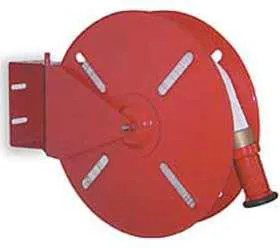
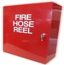
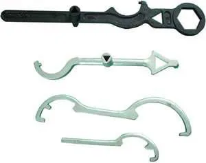
Stowed conspicuously adjacent to the hydrant. Contains: one approved synthetic fire hose (flaked or rolled), one dual-purpose jet/spray nozzle, and the dedicated coupling spanner wrench.
International Shore Connection (ISC)
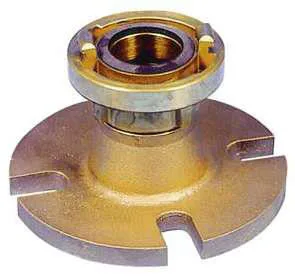
Standardized universal flange carried on board. Enables the ship to couple instantly to any municipal or shipyard fire tender worldwide during port layover or dry-docking.
Fastener Kit Specification
Must be stored with the ISC flange: 4 steel bolts of 16 mm diameter × 50 mm length, 8 flat washers, and 1 full-face non-asbestos elastomeric gasket rated for 10.5 bar.
Label the drawing: hydrant → anti-clockwise valve → flange → snap-in hose → dual nozzle, plus the hose box, spanner and international shore coupling — every item the Q24 sketch plates show.