
Ship Fire Detectors: Heat, Smoke & Flame Types
Heat, smoke and flame detectors: where each is fitted, how each works, and the coverage areas, heights and spacings surveyors test you on.
Key Principles at a Glance 5 points
- Heat detectors guard hot machinery spaces — purifier room, boiler, main and auxiliary engine areas and incinerator — fitted overhead at least 0.5 m from the bulkhead and operating at 54–78 °C when temperature rises slower than 1 °C per minute.
- Each heat detector covers 37 sq m with 9 m spacing (4.5 m from bulkheads), backed by MSB, ESB and transitional emergency power; the three working types are bimetallic 55–160 °C, fusible link 55–180 °C and pneumatic rate-of-rise 57–82 °C.
- Smoke detectors guard accommodation, stairways, ECR, bridge, cargo spaces and galley, fitted at least 0.5 m from deckhead fittings, alarming at 2–12.5 percent obscuration per metre, each covering 74 sq m with 11 m spacing (5.5 m from bulkheads).
- Smoke detection works by ionisation, light-obscuration or light-scatter principles; flame detection works in the infra-red and ultra-violet bands.
- Detector choice follows the space: heat where smoke would false-alarm (machinery, galley), smoke where early warning matters (accommodation, escape routes), flame where hydrocarbon fires flash fast.
1. Detector Family Tree — Say It First
For "what detector types do you have?" (Q20), draw the family tree before going deep — the surveyor wants to hear all three families and every sub-type in one breath:
The three families and their sub-types:
- Heat detectors: fixed-temperature bimetal strip type, rate-of-rise temperature type, fusible-link type, and fusible-alloy type.
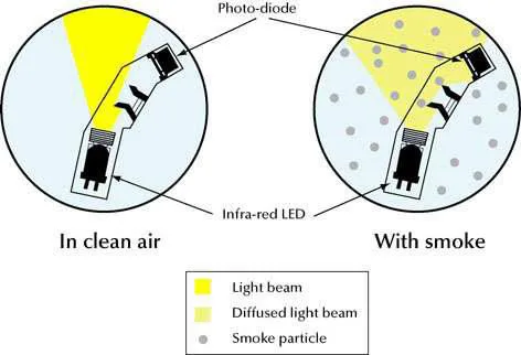
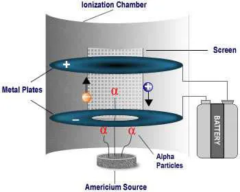
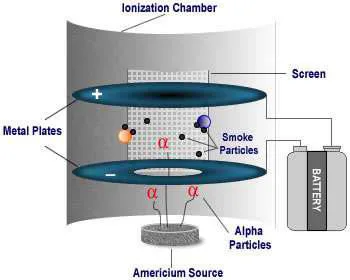
- Smoke detectors: ionisation type, light-obscuration type, and light-scatter type.
- Flame detectors: infra-red (IR) type and ultra-violet (UV) type.
The file recommends the simple detector sketch from the SCI AFF course booklet — draw that one, not a catalogue diagram. If the surveyor wants more, he will tell you to read the SCI AFF manual.
Heat Detectors
Locations: Purifier room, boiler platform, main/auxiliary engine tops, incinerator flat (hot, oily spaces where smoke heads false-alarm).
Specs: Max 37 m² area, 9 m spacing, 4.5 m from bulkhead. Alarms between 54 °C and 78 °C.
Smoke Detectors
Locations: Accommodation corridors, cabins, stairways, Engine Control Room (ECR), wheelhouse, cargo holds, galley.
Specs: Max 74 m² area, 11 m spacing, 5.5 m from bulkhead. Alarms at 2% to 12.5% obscuration per metre.
Flame Detectors
Locations: Fuel oil booster modules, burner fronts, paint lockers, helicopter decks.
Specs: Senses Infra-Red (IR) or Ultra-Violet (UV) radiation from open hydrocarbon flames. Instantaneous response to flash fires without waiting for smoke or heat accumulation.
2. Heat Detectors — Locations & Types
For "where are heat detectors fitted and how do they work?", start with the hot spaces where smoke detectors would false-alarm:
- Locations: mainly in the purifier room, near the boiler platform, around the main engine and auxiliary engines, and near the incinerator — anywhere hot, oily and smoky in normal operation.
- Position: located on the overhead, at a minimum distance of 0.5 m away from the bulkhead — except in corridors, lockers and stairways.
- Operation: operates before the temperature exceeds 78 °C, but not until the temperature reaches 54 °C, when the temperature rises within those limits at a rate less than 1 °C per minute.
- Coverage (regulation): maximum 37 sq m floor area per detector, maximum 9 m apart between centres, maximum 4.5 m away from bulkheads.
- Power supply: from the MSB, ESB and transitional battery.
Three working types — how each closes the circuit:
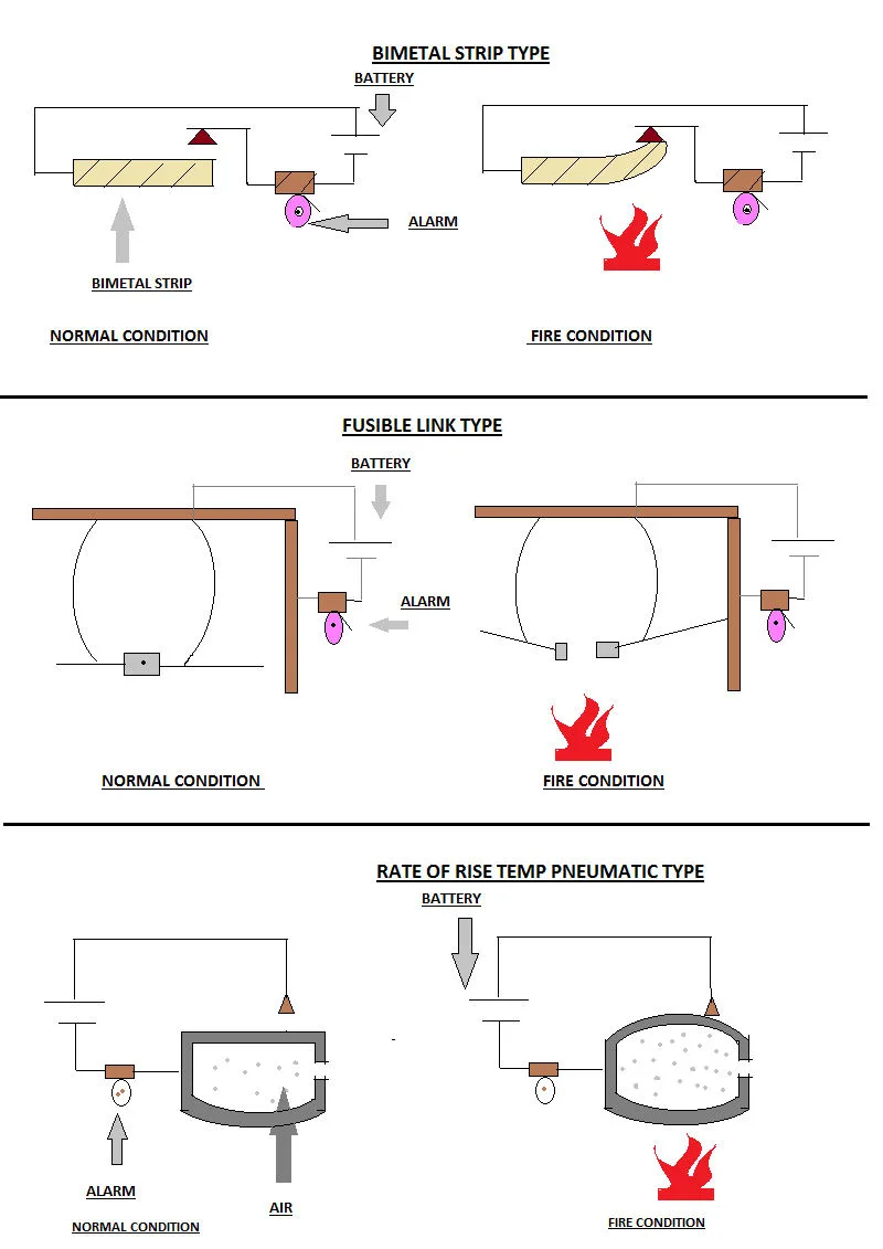
- Bimetal type (working range 55 °C to 160 °C): a bimetal strip with alarm and power-supply connections. In normal condition the strip does not bend, but in a fire it starts to bend, touches the contact point, closes the circuit, current flows and the alarm sounds. It takes some time to return to its natural position because of the bimetal property — the slow recovery the surveyor listens for.
- Fusible-link type (working range 55 °C to 180 °C): the principle is the same — once the circuit closes, the alarm sounds. The fusible link holds two connections together; in a fire it parts, one connection touches the plate, closes the circuit and the alarm sounds.
- Rate-of-rise pneumatic type (working range 57 °C to 82 °C): inside the detector casing is atmospheric air; in a fire the air expands with heat and the diaphragm in the upper part expands with it, touches the plate, closes the circuit and the alarm sounds.
Machinery spaces are hot, oily and smoky in normal operation — a smoke head would alarm all day. Say heat detection where heat is the reliable signature and the surveyor nods.
3. Smoke Detectors — Locations & Principles
For "where are smoke detectors fitted?", walk the accommodation and escape routes:
- Locations: places like accommodation, stairways, ECR, bridge, cargo spaces and around the galley — anywhere early warning saves lives.
- Position: located on the overhead, at a minimum distance of 0.5 m away from the bulkhead — except in corridors, lockers and stairways.
- Operation: operates before the smoke density exceeds 12.5 percent obscuration per metre, but not until it reaches 2 percent.
- Coverage (regulation): maximum 74 sq m floor area per detector, maximum 11 m apart between centres, maximum 5.5 m away from bulkheads.
- Power supply: from the MSB, ESB and transitional battery.
Three working principles — how each senses smoke:
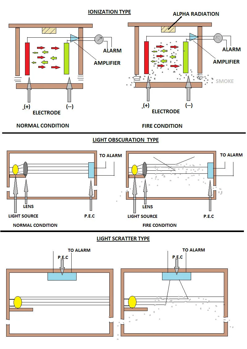
- Ionisation type: the detector holds positive and negative charged plates in a chamber. Positive ions are attracted to the negative plate and vice versa; the movement of ions reduces the resistance of the air, so a small current flows in the circuit, amplified so it can be readily monitored. In a fire, smoke particles entering the chamber attach to the ions, ion flow falls, resistance rises and the current falls — the amplifier senses the fall below the set value and gives the alarm.
- Light-obscuration type: works on the photo-electric cell principle. In normal condition the light source focuses on the PEC; in a fire, smoke entering the chamber reduces the light falling on the PEC and the alarm sounds.
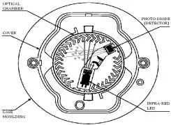
- Light-scatter type: works opposite to the obscuration type — when the light source focuses on the PEC it gives the alarm, the scattered beam reaching the off-axis sensor triggering the circuit.
Cabins, stairways and the ECR need the earliest possible warning while people sleep or escape — smoke reaches the head long before heat does. Quote 2–12.5% obscuration to show you know the sensitivity band.
4. Flame Detectors & the Spacing Table
Flame detectors watch for the radiation of open flame itself:
- Infra-red (IR) type: senses the infra-red radiation band of open flame — the heat-radiation signature of hydrocarbon fires.
- Ultra-violet (UV) type: senses the ultra-violet radiation band of open flame — the short-wave signature of the flame front.
- Fitted where a flammable-liquid fire would flash before smoke or heat builds — fuel-handling and high-risk machinery areas.
- Location defence (Q20b): heat in purifier, boiler, main and auxiliary engine, incinerator spaces; smoke in accommodation, stairways, ECR, bridge, cargo, galley; flame where hydrocarbon flash outruns smoke and heat.
- Exam habit: name the family, then the sub-type, then the numbers — for example "smoke, ionisation, 74 sq m on 11 m centres, alarming at 2 to 12.5 percent" — before explaining how it works.
- Surveyor sketch: offer the SCI AFF booklet drawing first; it is the simple circuit-closes-alarm sketch the file recommends, and it covers bimetal bend, fusible-link parting and diaphragm lift in one diagram.
Detector regulation — the one table to memorise (Q20a):
| Detector | Area per head | Spacing | Max from bulkhead | Position rule |
|---|---|---|---|---|
| Heat | 37 sq m | 9 m | 4.5 m | Overhead, ≥ 0.5 m off bulkhead |
| Smoke | 74 sq m | 11 m | 5.5 m | Overhead, ≥ 0.5 m off bulkhead |
- Heat operating band: 54–78 °C at a rise below 1 °C per minute; type ranges bimetal 55–160 °C, fusible link 55–180 °C, pneumatic 57–82 °C.
- Smoke alarm band: 2–12.5% obscuration per metre.
- Both types: 0.5 m clear of the bulkhead except in corridors, lockers and stairways.
- Heat and smoke power supplies: MSB + ESB + transitional battery.
5. Exam Drill — Choosing & Defending Detectors
Close the chapter the way the surveyor closes the question — "why this detector in this space?" (Q20b):
- Purifier room smoking slightly? Heat head — smoke would false-alarm; heat at 54–78 °C is the reliable signature.
- Cabin corridor at night? Smoke head — earliest warning at 2–12.5% obscuration per metre while people sleep.
- Engine-room fringe spaces? Heat head near the boiler platform and incinerator where exhaust haze would blind a smoke chamber.
- How many heads for a 150 sq m hold? Smoke covers 74 sq m — two heads minimum, within 11 m spacing and 5.5 m of bulkheads.
- Bimetal slow to reset? Say the property of the bimetal holds it bent — that slow recovery is expected, not a fault.
- Fusible link after fire? The parted link is a one-shot trip — the head needs a new link before it can guard again, unlike the self-recovering bimetal and pneumatic types.
- Regulation vs location split: Q20a wants the area, spacing and bulkhead triplets; Q20b wants the space list per family — answer the asked half first, then offer the other.
- Obscuration wording: say per metre after 2–12.5 percent — the unit is part of the mark.
- Position exception: the 0.5 m rule falls away only in corridors, lockers and stairways — everywhere else, quote the clearance before the coverage triplet.
Recite cold: heat 37 / 9 / 4.5, smoke 74 / 11 / 5.5, heat 54–78 °C (bimetal 55–160, fusible 55–180, pneumatic 57–82), smoke 2–12.5%, both 0.5 m clear. That single sentence answers half the detector questions.