
The Bilge System the Separator Serves
The pipework and the discipline that feed the separator and, more importantly, the arrangements that let a ship deal with a flooded engine room.
Key Principles at a Glance 7 points
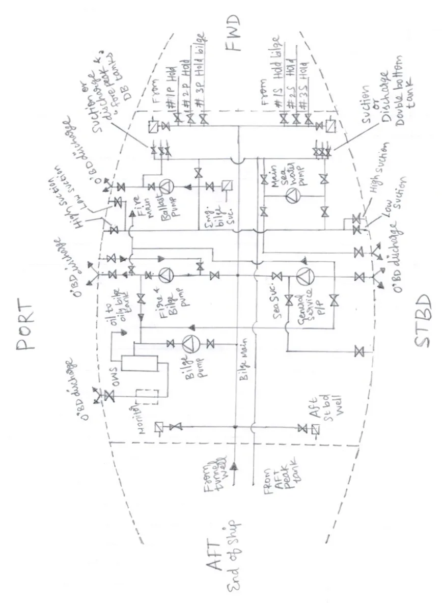
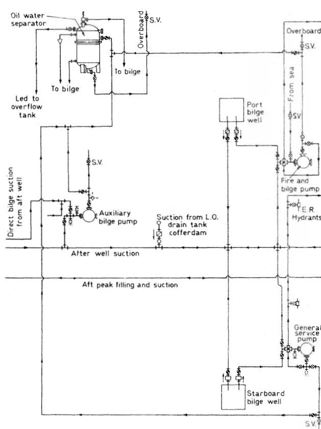
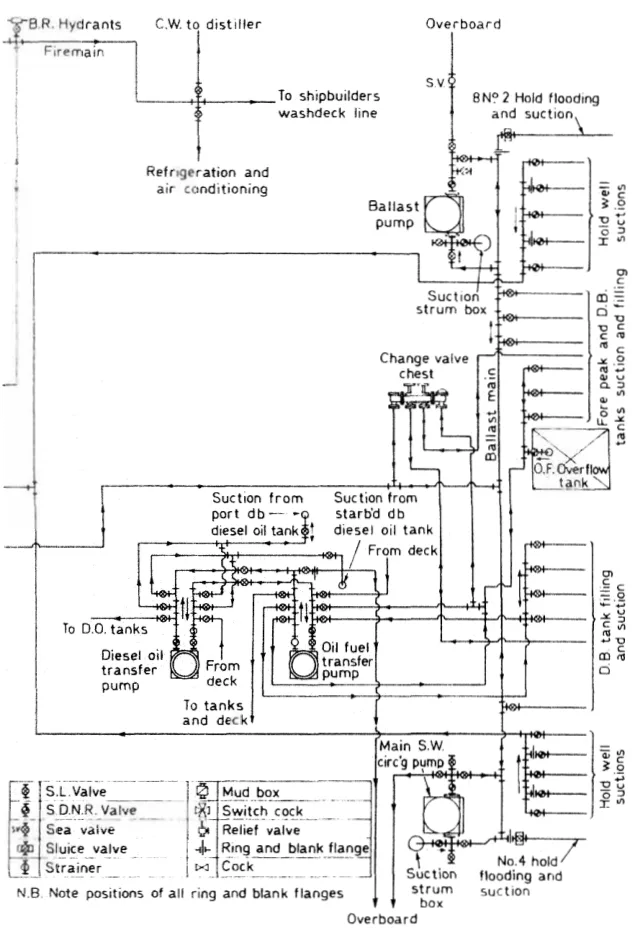
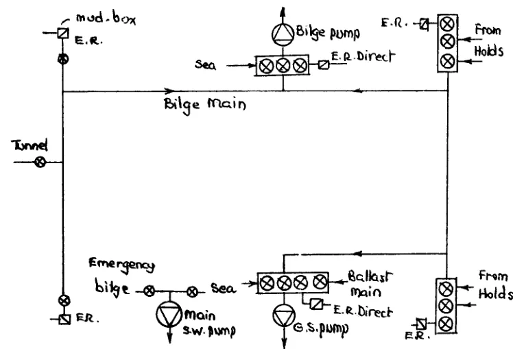
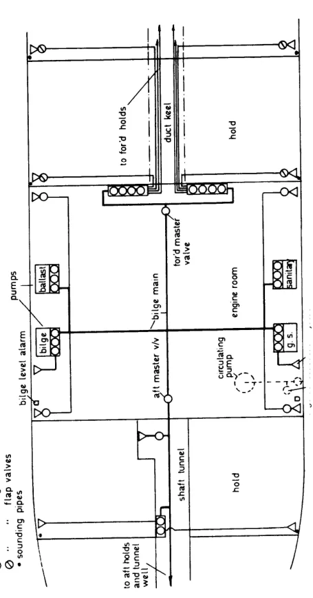
- The arrangement is the main bilge line carrying the branch suctions, two bilge suctions in the machinery space, and the bilge injection leading to the main sea water cooling pump suction line.
- Seven rules: the system is entirely separate from other systems; two bilge pumps with direct suctions each side; no mud box or strum box on the emergency suction; mud boxes at platform level with straight tail pipes; self-priming pumps; a screw-down non-return valve on each suction; and the separator on the discharge side of the bilge pump.
- The mains are at least 63.5 mm bore and the branches at least 50 mm, and the direct suctions are never smaller than the main bilge line — in a flooding emergency the direct suction is what is used.
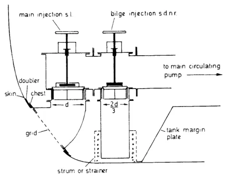
- The bilge injection is the same size as the cooling pump's suction branch in a motor ship and two-thirds of that in a steam ship, and it carries no strainer by deliberate design.
- Bilge pipes are not led through oil tanks or double bottom tanks, and the bilge system is kept separate from the cargo and oil fuel systems.
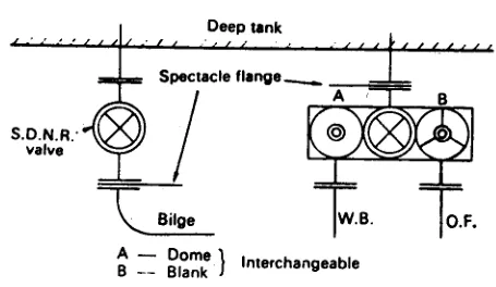
- The overboard discharge valve is kept tight closed under chain and lock and the bilge connection is blanked by a blind flange, because a closed valve can leak past its seat and a blanked flange cannot.
- At sea use the direct bilge suction, and the bilge injection only in dangerous flooding — opening it puts sea water into the engine room as well as taking water out.
1. The arrangement
The bilge system is a statutory system. The overboard discharge valve is kept tight closed under chain and lock, and the bilge connection is blanked by a blind flange. No change to the bilge system is made without the Chief Engineer's authority.
The principal features of the machinery space bilge system are the main bilge line, to which the suctions from the various compartments connect, and two bilge suctions in the machinery space. In addition there is an emergency bilge suction led to the main sea water cooling pump suction line — this is the bilge injection.
The sizes
- Motor ships — the bilge injection is the same size as the suction branch of the cooling sea water pump. Steam ships — two-thirds of that size.
- One branch and one direct bilge suction on each side of the machinery space, and the direct suctions are not smaller than the main bilge line.
- The bore of the mains is at least 63.5 mm, and the branches at least 50 mm, with the branches not needing to exceed 100 mm.
The reason the direct suctions must be as large as the main is straightforward: in a flooding emergency, the direct suction is what is used, and a restriction there would defeat the purpose.
2. The seven rules
These are the requirements a bilge system is built to, and they are commonly asked as a straight list:
- The bilge system is entirely separate from other systems.
- The main bilge connects to two bilge pumps, and there are direct bilge suctions on each side, port and starboard.
- The emergency bilge suction leads to the main cooling sea water pump suction line. Fitting a mud box or strum box on this line is avoided — they clog, and when the suction is actually needed the free area through the holes may not be there.
- Direct bilge suctions in the machinery space and tunnel have mud boxes at platform level, easily accessible, with straight tail pipes.
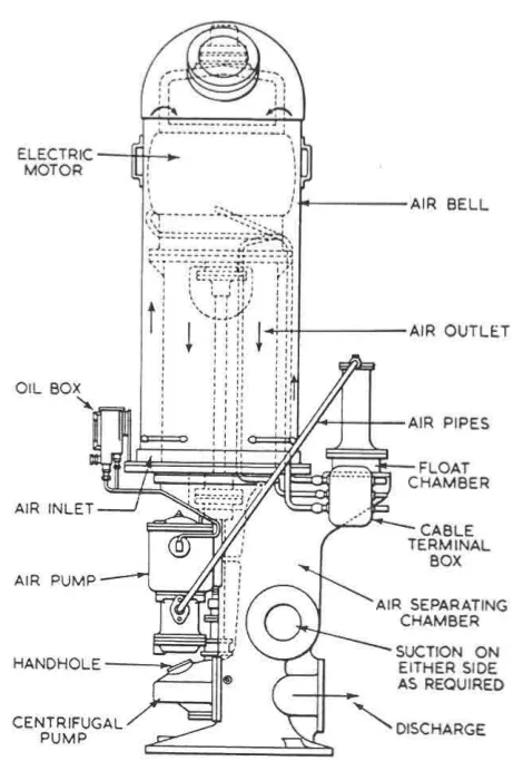
- The bilge pumps are self-priming, or quickly primed.
- Each suction has a screw-down non-return valve, to prevent inter-communication between compartments and between lines.
- The oily water separator is fitted on the discharge side of the bilge pump, to prevent the discharge of oil overboard.
Two further points go with these. Bilge pipes are not led through oil tanks or double bottom tanks, and the bilge system is separated from the cargo and oil fuel systems.
3. The bilge injection
The bilge injection is the emergency connection between the bilge system and the main sea water cooling pump suction. The valve is of the screw lift, screw down type. There is no mud box and no strainer on this line. It is used in the event of engine room flooding, and in emergency.
The absence of a strainer is deliberate and is worth explaining rather than merely stating. A strainer on the bilge injection line would clog with the very debris a flooding casualty stirs up, at exactly the moment full flow is needed. A clean bore with nothing in it is more useful than a protected bore that blocks.

Action if the bilge is flooded
- At sea — use the direct bilge suction. Use the bilge injection valve only in dangerous flooding, since opening it puts sea water into the engine room as well as taking water out.
- In port — put the water into the bilge tank, or send it to shore if the ship is not capable of dealing with it on board.
The caution on the bilge injection is real. The valve admits sea water into the machinery space; it is a pump-out arrangement only in the sense that the cooling pump can then discharge the mixture overboard. Opening it in a merely inconvenient amount of water turns a nuisance into a casualty.
4. The overboard valve discipline
The overboard discharge valve is the single point at which a mistake becomes a pollution offence, and it is treated accordingly.
The bilge overboard discharge valve must be tight closed and kept under chain and lock. The bilge connection must be blanked by a blind flange, and that connection must be absolutely free from oil and sludge.
The bilge tank must be made ready and the water transferred to it. Oil leakage must be minimised and the increase of machinery space bilge water controlled.
The blind flange matters as much as the lock. A closed valve can leak past its seat, particularly a valve that has been sitting in oily water for years. A blanked flange cannot.
5. Bunkering precautions
Bunkering is when the largest volume of oil is being moved on board and when a spill is most likely, so the precautions are specific:
- All scuppers plugged, so that a deck spillage is contained on deck rather than going over the side.
- Drip trays under the ship-shore connection.
- Good communication between ship and shore throughout the operation.
- Personnel fully conversant with the layout of pipes, tanks and valves involved.
- Moorings and hose length arranged so that the hose cannot stretch or be crushed as the ship moves on her lines.
- The blank at the opposite end of the cross-over pipe securely in place.
- Air pipes clear, soundings checked, and depth indicators tested.
When transferring oil within the ship, the same care applies: ideally work in daylight, with overboard discharge connections closed and secured, the overflow alarm tested, and soundings taken frequently. Avoid using empty oil fuel tanks as ballast tanks — a tank that has held oil and is then used for ballast produces oily ballast water, which is a problem the ship has created for itself.
6. Keeping oil out of the bilges
The cheapest way to deal with oily bilge water is not to make it. No oil leak should be tolerated — oil tank trays and drip pans, fuel and lube oil separator trays, valves, burners and piping connections are all checked and kept clean. The tank top and bilges are cleaned and hosed down frequently.
A machinery space that is kept clean produces bilge water that is close to legal on its own. A machinery space that is not produces a bilge tank full of emulsion that no separator can deal with at a sensible throughput, and a sludge problem to go with it.