
Inside the Oily Water Separator — Plates, Probes, Relief Valve and Siphon Breaker
What the oily water separator actually looks like inside, how the flow path works, and what every fitting on the shell is for.
Key Principles at a Glance 6 points
- The classic unit is a vertical cylindrical pressure vessel containing a stack of inverted conical plates, with an oil collecting dome on top.
- The plates are coalescing surfaces and not merely settling area — oil is trapped by their undersurfaces and grows until it breaks away at the periphery, which is why sludge on the plates costs performance.
- The first stage drains oil automatically on a capacitance probe, solenoid pilot valve and diaphragm-controlled piston valve; the second stage is drained manually at intervals through the cocks.
- Three probes: two at the highest and lowest levels of the oil-water interface, and a third low in the clean water space as the emergency cut-out should priming-over occur.
- Working pressure is about 2 bar, the relief valve is set at about 2½ bar, and a relief valve is fitted on each stage — led back to the pump suction or an overflow tank, never overboard.
- The siphon breaker — anti-siphon valve or vented loop — is the only thing stopping a stopped separator emptying itself overboard unattended.
1. The Simplex-Turbulo construction
The maker's manual governs the internal clearances, the plate pack, the probe settings and the relief valve setting. Never open the separator for internal work without the Chief Engineer's authority and the overboard valve locked shut.
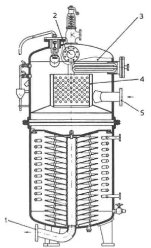
The classic shipboard separator is a vertical cylindrical pressure vessel containing inverted conical plates. It is worth picturing: a tall steel cylinder standing on a flanged base, with the plate pack stacked inside it and an oil collecting dome on top.
The flow path
- Oily water enters the upper half of the vessel and is directed downwards onto the conical plates.
- Large globules separate in the upper part, before the mixture reaches the plates at all.
- Smaller globules are carried into the spaces between the plates. They are trapped by the under-surfaces of the plates and coalesce there until they have enough rising velocity to travel along the plate surface and break away at the periphery.
- Oil rises, is caught under an annular baffle, and is led up through the risers to collect in the dome at the top of the vessel.
- Water leaves the plate pack through a central pipe and out through a flange at the base.
The important detail is step 3. The plates are not merely a large settling area; they are angled surfaces on which oil accumulates and grows. A separator that is working properly is one in which the plates are doing the coalescing, and that is why the plates have to be kept free of sludge.
The fittings on the shell
- Two test cocks, used to observe the depth of oil in the dome. When oil is seen at the lower test cock, the oil drain valve must be opened. This is the manual check that tells you whether the automatic drain is doing its job.
- An automatic air release valve in the dome, to let air out as the vessel fills.
- An electronically operated oil drainage valve, working from liquid level probes. Visual and audible oil overload indicators may also be fitted alongside it.
- Steam coils or electric heaters in the upper part of the vessel. Additional coils in the lower part are fitted for high-viscosity oils, where heating matters more.
2. The first stage in more detail
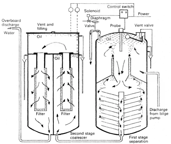
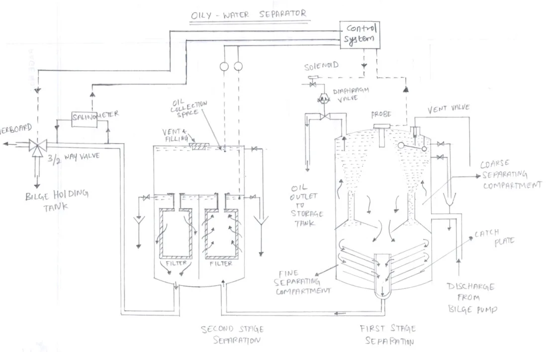
In the Turbulo arrangement, separation begins in the top of the chamber by density difference, and continues in the lower chamber through dished plates, with oil collecting at the baffles and funnelling up to the oil collection space.
Oil arriving at the top is automatically drained to the oil tank, and air is vented by a float controlled release valve.
The oil drain valve itself is a diaphragm controlled piston valve, with control air admitted through a solenoid operated pilot valve. A capacitance probe senses the quantity of oil present and energises the solenoid through the control switch. So the chain runs: oil level rises → capacitance changes → control switch operates → solenoid energises → pilot valve admits control air → diaphragm moves the piston → oil drains.
Water passes down through a central pipe to the second stage coalescer. In the second stage, the right hand chamber filter removes solids and some oil, and the left hand chamber coalescing inserts remove the rest. Second stage oil is drained manually at intervals through the cocks — unlike the first stage, this one is not automatic. Final discharge is below 15 p.p.m.
3. Automatic operation
Watching an automatic separator start up is the clearest way to understand it:
- Clean water is delivered until it discharges from the vent valve, which is then closed. The vessel is primed with clean water before any oily mixture is admitted.
- Oily water is admitted. At about 2 bar the water discharge valve opens automatically.
- The mixture circulates across weirs and perforated baffles.
- Oil accumulates at the top. As the interface moves down, the oil discharge valve opens automatically.
- A bypass pipe takes traces of oil from the last stage back to the top, so that anything not caught on the first pass gets another one.
Steam heating coils in the oil space reduce viscosity and assist separation, and the test cocks give an approximate check on the automatic detection — the manual cross-check on an automatic system.
4. The electric probe and the alarm circuit
This is the part of the machine that most repays learning properly, because it is where most faults show up.
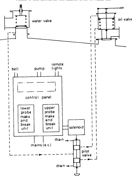
Two sheathed probes sit at the highest and lowest levels of the oil-water interface. A third probe is fitted low down in the clean water space — this third one is the emergency cut-out should priming-over occur.
How the probe works
The probe and the tank form the two electrodes of a variable condenser. The capacitance of that condenser depends on the dielectric constant of whatever material lies between them. The bridge circuit is balanced in air. When the material between the electrodes changes from air to oil, or from oil to water, the dielectric constant changes, the bridge goes out of balance, and the resulting signal operates lights, alarms, or — preferably — solenoid valves through air, steam or hydraulic servos.
The sequence to learn
| Condition | What happens |
|---|---|
| Separator empty — both probes in air | Probe lamps out; oil discharge lamp on; contactor energised; solenoid energised; pilot valve up; alarm bell ringing; pump tripped |
| Water reaches the lower probe | Bell stops; lower probe lamp on |
| Water reaches the upper probe | Upper probe lamp on; water discharge lamp on; oil discharge lamp out; solenoid de-energised; pilot valve moves down |
The sequence reverses when oil pushes the interface down — that is, when enough oil has collected to displace the water level downwards, the upper probe comes out of the water and into oil, and the valve arrangement reverses to drain oil instead.
The main isolator
With the main isolator shut, the lower probe can isolate and cut out the pump if oil reaches the danger level. With the main isolator open, this protection is shorted out, so that the pump can be used for other duties.
That is a genuine operational hazard as well as an exam point. Opening the main isolator to use the pump elsewhere removes the protection that stops the separator filling with oil.
5. The relief valve — mandatory
A relief valve on the shell, or on the incoming mixture line, is essential. Its purpose is to prevent overpressure and the resulting accidental discharge to a confined space or overboard under all working conditions. It should be led back to the suction side of the supply pump, or to an overflow tank — never to a place where the discharge would endanger anyone or put oil into the sea.
The pressure figures to hold:
- Working pressure is about 2 bar — this is the setting of the spring loaded water discharge valve.
- The relief valve is set at about 2½ bar, comfortably above the working pressure.
- A relief valve is fitted on each stage, not just on the first.
6. The siphon breaker
A siphon is an inverted U-shaped pipe which can cause liquid to flow upward, above the surface of a reservoir, without a pump. Once a siphon is established it will keep running on its own, and that is exactly the problem for an oily water separator.
Why the separator needs a siphon breaker: when the outside head is greater than the inside, the siphon will not let the oily mixture go overboard — the sea holds it back. But when the separator is stopped and the outside head becomes less than the inside head, the siphon would let the oily water escape overboard and pollute. The machine would discharge itself, unattended, while shut down.
The remedy is a siphon breaker, also called an anti-siphon valve or a vented loop. It is a small vent at the top of the discharge loop. Air enters the pipe through the vent and the water level drops away from the loop on both sides, which breaks the siphon.
This is a small fitting with a large consequence. Its failure is the reason a separator can be found discharging with the pump stopped and the overboard valve shut.
7. Mountings and safety devices
The mountings on the vessel: capacitance probe for oil level, air vent, relief valve, test cock, drain valve, solenoid, diaphragm, and the 15 p.p.m. monitor.
The safety devices on the installation: a pressure relief valve on the discharge pipe; the oil discharge monitoring system with a high p.p.m. alarm and an automatic pump stopping device; a test cock; and a drain valve.
The pattern is worth noting. The relief valve protects the vessel. The monitoring system protects the sea. The test cocks and drain valve are the manual means by which the operator confirms that both of the automatic systems are telling the truth.