

Fin Stabilizers & Anti-Roll Tanks — Denny-Brown Folding Fins, Hydraulic Tilting and Flume Systems
Master ship roll stabilization: active hydrofoil fins, Denny-Brown folding fins, hydraulic tilting gear, gyroscopic multi-term control, and passive flume tanks for MEO exams.
1. Ship Rolling Dynamics & The Stabilization Problem
Warning: Operational & Structural Impact
Unchecked resonant rolling in a beam seaway can cause severe container lashings failure, cargo shift, crew exhaustion, and excessive machinery dynamic stresses. Fin stabilizers do not increase static stability; they apply an active dynamic counter-moment to suppress wave-induced roll amplitudes.
A ship rolling freely in calm water behaves as an oscillatory pendulum. Its natural rolling period (Tr) depends upon its mass moment of inertia and metacentric height (GM):
Tr = 2π · k√(g · GM) = C · B√(GM)
where k is the radius of gyration, B is the ship beam, and C is an empirical constant (typically 0.70 to 0.85). In loaded cargo vessels with high GM, the ship is "stiff" with a short, violent roll period; in passenger vessels with moderate GM, the roll period is longer and gentler.
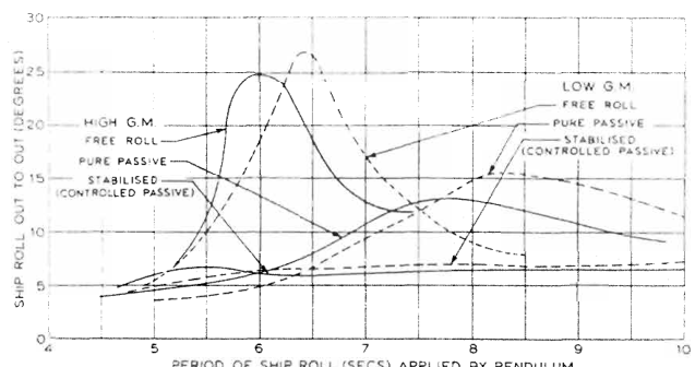
When the encounter period of regular beam ocean waves coincides exactly with the natural roll period of the vessel (Te ≈ Tr), **synchronous or resonant rolling** occurs. Wave energy pumps into the hull with every cycle, rapidly magnifying roll amplitudes from a modest 5° to dangerous excursions exceeding 25° to 30° out-to-out.
Wave Heeling Moment
For small heel angles θ (in radians), the wave heeling moment is Mheel = W · GM · θ, establishing the exact force the stabilizer must generate to maintain the ship on an even keel.
Bilge Keels Limit
Passive bilge keels welded at the turn of the bilge provide hydrodynamic vortex damping, but their roll energy dissipation is limited to roughly 15% to 25% of total roll energy.
Active Roll Suppression
Active fin stabilizers apply dynamic hydrodynamic forces that reduce resonant roll angles by 85% to 92% (e.g., cutting a 30° roll out-to-out down to under 3°).
2. Hydrofoil Lift Mechanics & The Angle of Attack
Fin stabilizers operate on the identical aerodynamic principle as an aircraft wing. When a streamlined hydrofoil section moves horizontally through seawater at ship speed (V), water splits across the upper and lower profiles.
When the leading edge of the starboard fin tilts upward (positive angle of attack α):
- Water traveling over the curved upper surface accelerates, inducing a localized pressure drop according to Bernoulli's equation (P + ½ρv² = constant).
- Water passing under the lower surface decelerates, generating increased static pressure.
- The net pressure differential produces a powerful vertical upward **Lift Force (L)** on the starboard side.
Simultaneously, the port fin tilts downward at an identical negative angle of attack, creating an equal downward force. The product of this vertical push-pull force and the athwartships distance between the fin centers (Bfin) forms a powerful **stabilizing couple** that counteracts the wave rolling moment:
Mstabilizing = L × Bfin = (½ρ · A · V² · CL) × Bfin
Danger: The Speed-Squared Law (V²)
Because lift is proportional to the **square of forward speed (V²)**, halving a ship's speed from 20 knots to 10 knots slashes stabilizing power by **75%**. At zero speed (e.g. at anchor or adrift), active fins produce zero lift and function merely as passive dead appendages.
3. The Fin Flap — Multiplying Hydrodynamic Lift
If a simple, un-flapped symmetrical hydrofoil is tilted beyond an angle of approximately 15° to 18°, the boundary layer separates violently from the suction side, causing sudden hydrodynamic **stall**—lift collapses while drag skyrockets.
To overcome this limitation, high-performance marine stabilizers incorporate a **hinged trailing-edge flap** (the Denny-Brown slotted flap principle):
Camber Doubling
As the main fin tilts through angle α (typically up to ±25°), an internal mechanical quadrant or linkage deflects the trailing flap an additional 10° to 15° in the same direction.
Lift Coefficient Boost
The flapped profile increases the maximum lift coefficient (CL) from ~1.0 to over **1.8**, nearly doubling the lift per square metre of fin area without triggering stall.
Hull Volume Savings
Because each square metre generates nearly twice the thrust, the overall fin span and chord are reduced by 30% to 40%, drastically shrinking the internal hull fin box required to house the machinery.
4. Retractable vs Non-Retractable Fin Typologies
Stabilizer installations are divided mechanically into three design classes depending upon ship type, hull envelope constraints, and available internal space:
1. Non-Retractable Fins
Permanently external fins mounted at the turn of the bilge, supported by a heavy hull-mounted cruciform flange. Crucially, the fin geometry is dimensioned so it does not project beyond the maximum vertical line of the ship’s side plating or below the horizontal baseline of the keel. This protects the fin from striking quay walls during berthing or touching bottom in shallow docks.
2. Athwartships Retracting Fins (Denny-Brown)
The classic Denny-Brown system extends and retracts horizontally into a transverse hull housing known as the **fin box**.
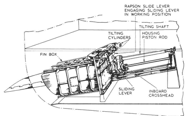
Mechanical layout of the athwartships retracting fin:
- The Fin Box: A fabricated watertight steel box welded into the double bottom and bilge structure, open to the sea at the hull shell.
- Internal and External Crossheads: The cylindrical fin shaft passes through a sliding cruciform crosshead mounted on heavy horizontal guide bars. When housed, the fin slides completely inside the hull, sealed from the machinery space by multiple gland packings.
- Length Penalty: Because the fin shaft must be retracted straight inboard, the complete assembly demands an internal athwartships width greater than **twice the fin length**—a major spatial penalty on beam-restricted vessels.
3. Forward-Folding Fins (Denny-Brown-AEG)
To eliminate the transverse width penalty of athwartships retraction, the **forward-folding fin** hinges horizontally into a shallow triangular hull recess:
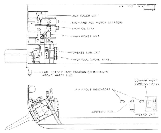
When stowed, hydraulic actuators swing the fin forward around a massive vertical trunnion hinge pin. The fin nests flush inside a triangular hull pocket, completely freeing up the central machinery space for generators, coolers, and boilers.
5. Hydraulic Tilting Gear & Mechanical Actuation
Rapid fin reversal is essential: to counter ocean waves with periods of 6 to 10 seconds, the fin must cycle from full positive tilt (+25°) to full negative tilt (-25°) in under **1.5 to 2.5 seconds**.
The tilting power unit mirrors steering gear engineering:
- Variable Delivery Swash-Plate Pumps: Driven by constant-speed electric motors. Swashplate tilt dictates oil flow rate and direction to the tilting rams.
- Double-Acting Opposed Tilting Rams: Two hydraulic rams act on a heavy tiller arm keyed directly to the fin shaft crosshead. Admitting high-pressure oil (140 to 210 bar) to one cylinder forces the tiller over, rotating the fin in its sleeve bearings.
- Mechanical Locking Pin: When the fins are housed inside the hull, a hydraulically operated mechanical locking pin engages into the crosshead or trunnion. This mechanically locks the fin in zero position, preventing hydrodynamic flutter or wave slap from dislodging the stowed gear.
6. Gyroscopic Sensing & Multi-Term Control (Multra System)
If fins were controlled solely by roll angle, maximum tilt would occur when the ship reaches maximum roll. But by that point, roll velocity is zero and the wave has already imparted its energy. Effective roll suppression requires **anticipatory control**.
The Denny-Brown **Multra Control System** integrates gyroscopic sensing to calculate a composite tilt demand signal:
Roll Angle (θ)
Sensed by a vertical-keeping gyroscope. Provides restoring force proportional to displacement from the upright.
Roll Velocity (θ̇)
Sensed by a spring-restrained rate gyroscope. Produces a 90° phase advance, damping roll momentum at the moment of highest angular velocity.
Roll Acceleration (θ̈)
Obtained by electrically differentiating the rate signal. Anticipates impact forces from sudden steep rogue waves before roll develops.
The Natural List Integrator
Vessels frequently experience a steady heel due to steady beam winds, uneven cargo distribution, or passenger movement. If the stabilizer attempted to fight this steady list, the fins would remain permanently deflected at high angle, producing massive drag, slowing the vessel, and consuming enormous fuel.
A **natural list unit** (a low-pass hydraulic or electronic integrator) filters out steady heel angles lasting longer than 30–45 seconds, adjusting the control zero-point so the fins stabilize the vessel *about its mean angle of heel*, completely avoiding continuous hydrodynamic drag.
7. Passive Anti-Roll Tanks (Flume & Brown-NPL Systems)
While fin stabilizers excel at cruising speeds, they fail when vessels are stationary—such as drillships, oceanographic survey vessels, cable layers, and anchored cruise liners. Here, **passive anti-roll stabilizing tanks** provide roll suppression without moving underwater parts.
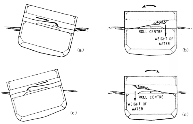
Working Principle: Phase Lag Damping
A passive anti-roll tank consists of two wing tanks connected athwartships by a deep liquid channel (utilizing water or fuel oil), forming a massive U-tube:
- Tuned Natural Frequency: The dimensions of the cross-duct, the liquid depth, and internal baffles are calculated so that the liquid’s natural sloshing period equals the ship's natural rolling period (Tfluid ≈ Tr).
- Quarter-Cycle Phase Lag (90°): As the ship rolls to starboard, the liquid begins transferring across. Due to the hydraulic resistance of internal constriction nozzles or perforated baffles, the liquid wave lags **90 degrees out of phase** with ship motion.
- Opposing Moment: By the time the ship finishes rolling to starboard and starts swinging back toward port, the bulk of the water mass arrives in the starboard tank, holding it down and directly opposing the return roll velocity.
8. Anti-Heeling Systems for Cargo Operations
Anti-heeling systems differ fundamentally from stabilizing tanks: their purpose is not to damp dynamic sea waves, but to keep container ships, heavy-lift vessels, and Ro-Ro ferries **strictly upright during rapid crane loading and vehicle transit**.
Automatic Ballast Transfer
Dedicated port and starboard wing ballast tanks are interconnected by a large cross-flooding pipe fitted with a high-capacity reversible axial-flow propeller pump (1,000 to 2,500 m³/h).
Compressed Air Displacement
On some installations, liquid is shifted even faster by injecting low-pressure compressed air into the top of the loaded tank, forcing ballast across into the opposite wing tank in seconds.
Inclinometer Auto-Control
Electronic clinometers sense a heel of as little as 0.5° to 1.0°, automatically commanding the transfer pump to shift ballast to the high side, preventing container guide-rail jamming.
9. Maintenance, Sea Chest Seals & Surveyor Clearance Checks
Because stabilizer fin shafts penetrate the hull below the waterline in way of high hydrodynamic turbulence, maintenance and seal integrity are rigorous examination items for Class surveys.
| Inspection Item | Standard Clearances & Criteria | Engineering Failure & Safety Risk |
|---|---|---|
| Fin Shaft Bearing Clearances | Synthetic composite (Thordon / Orkot) water-lubricated outer bearings: measure wear-down with poker gauge (max allowable 1.5 to 2.5 mm). | Excessive wear allows fin shaft chatter, severe vibration, and destruction of hull seals. |
| Hull Sealing Gland Packings | Double inflatable seal + multiple chevron rubber packing rings running on ceramic-coated sleeves. Test inflatable emergency seal before opening main gland. | Flooding of the stabilizer compartment through the hull fin box penetrations. |
| Hydraulic Oil Sampling | Monthly laboratory test for water-in-oil content (<0.1% max limit) and particle count (ISO 4406 cleanliness 16/14/11). | Water emulsion causes swashplate valve-plate seizure and catastrophic tilting pump failure. |
| Fin Box Sacrificial Anodes | Inspect zinc or aluminium anodes inside the water-filled fin box; renew if depleted over 50% by weight. | Severe galvanic pitting of the fin box shell structure and guide tracks. |
| Hinge Pin Trunnion Bushings | Check folding fin vertical hinge pins for fatigue cracks using MPI (Magnetic Particle Inspection); record radial clearance. | Structural failure of hinge pin under peak wave slamming loads, leading to total loss of fin at sea. |
Found a mistake, or something unclear?
Report it in a few seconds — it goes straight to the editors.