

Variable Injection Timing (VIT), Super-VIT & Engine Emissions
Master marine VIT and Super-VIT: engine-specific injection timing control, moving-barrel pump mechanisms, fuel-quality adjustment, electronic rate shaping, and NOx trade-offs.
The Thermodynamics of Injection Timing & SFOC Optimization
In an internal combustion diesel engine, the timing of fuel injection relative to the crankshaft position (crank angle degrees before top dead center, °BTDC) governs the entire combustion process. On older, fixed-timed marine diesel engines, fuel injection timing was mechanically calibrated for maximum design power (100% Maximum Continuous Rating, MCR).
The Fixed-Timing Part-Load Dilemma
When an engine with fixed injection timing operates at reduced load, its air supply, compression conditions and combustion pressure change. The resulting performance depends on the engine, load and fuel; maker indicator data should be used to assess it:
- Drop in Compression Pressure (Pcomp): At reduced load, the turbocharger delivers scavenge air at lower density and pressure, causing Pcomp to drop substantially.
- Severe Fall in Maximum Combustion Pressure (Pmax): Because injection timing remains fixed, combustion initiates relatively late in the cycle. The peak firing pressure (Pmax) drops far below the structural design ceiling of the engine.
- Deterioration of Thermal Efficiency: Classical thermodynamic cycle analysis demonstrates that thermal efficiency (ηth) and Specific Fuel Oil Consumption (SFOC) are directly determined by the pressure ratio across combustion (rp = Pmax / Pcomp) and the effective expansion ratio:
ηth = 1 − 1 rγ − 1 · rp · rcγ − 1 (rp − 1) + γ · rp · (rc − 1)
- Fuel consumption: Injection timing affects combustion phasing and specific fuel consumption, but the benefit depends on the engine tuning, load, fuel and operating condition. Use the maker’s test data rather than a universal savings figure.
The Economic Goal of Variable Injection Timing (VIT)
The purpose of variable injection timing is to adjust injection phasing with load so combustion pressure and efficiency can be managed within the engine’s design limits:
The Fundamental Principle of VIT: VIT changes the beginning of injection according to the engine’s load and tuning profile. In typical systems, timing is advanced through part load to help maintain firing pressure and then retarded as load rises toward full load. The breakpoint, pressure target and fuel-consumption benefit vary by engine; do not use a memorized percentage or savings value as a setting.
Mechanical VIT & Super-VIT Operating Principles
The classic mechanical VIT system developed by MAN B&W is known as Super-VIT. It translates engine load (sensed from the fuel pump regulating shaft) into an automated pneumatic control signal that dynamically adjusts fuel pump timing.
How a load-dependent VIT profile behaves
Mechanical Super-VIT adjusts injection timing in relation to engine load through the fuel-pump regulating mechanism. In typical configurations, timing advances as load rises through part load and is then retarded toward the full-load setting. This shape helps manage maximum firing pressure and part-load efficiency; it is not a universal three-zone breakpoint curve. The installed engine's manual defines the active range, breakpoint, mechanical stops, pressure limits and calibration method.
When discussing a VIT profile, describe the trend shown by that engine's diagram and verify the result with indicator measurements. A breakpoint such as 85% MCR or a pressure plateau must not be assumed for another engine or treated as a general operating target.
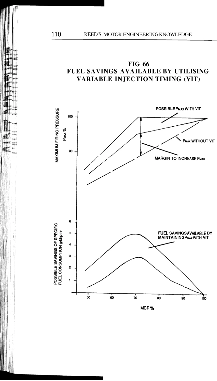
Fuel Pump Actuation Mechanisms: MAN B&W vs Sulzer/WinGD
To physically alter the start of injection while the engine is running under full load, engine designers developed distinct mechanical solutions.
1. MAN B&W MC Series: The Moving Barrel Mechanism
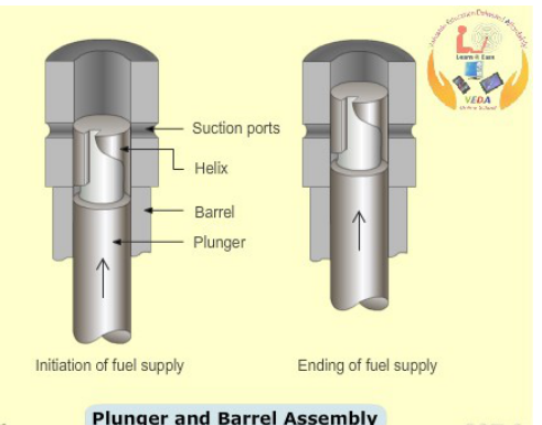
In conventional jerk pumps, the barrel is fixed rigidly to the pump housing. In the MAN B&W MC design, the pump barrel is movable vertically:
- Dual Rack-and-Pinion System:
- Upper Fuel Quantity Rack: Connected to the governor regulating shaft. It rotates the fuel plunger via a toothed control sleeve to alter the effective stroke (distance from spill port closure to opening of the lower helical spill groove), controlling fuel volume.
- Lower VIT Timing Rack: Connected to the pneumatic position servo. It rotates a threaded sleeve with coarse internal threads that engages external threads on the lower pump barrel.
- Vertical Translation of the Barrel:
- Advancing Timing: When the VIT rack moves, the threaded sleeve rotates, lifting the entire pump barrel upward. Because the barrel moves up while the camshaft roller follower position remains unchanged, the top edge of the ascending plunger blanks off the suction/spill ports earlier in the stroke! Injection begins earlier in crank angle degrees.
- Retarding Timing: The threaded sleeve rotates in reverse, lowering the barrel downward. The plunger must travel further upward before sealing the spill ports, delaying the start of injection.
- High-Pressure Erosion Plugs: When the plunger helix uncovers the spill ports at peak injection pressure (900–1,100 bar), supersonic jets of hot fuel oil blast outward. Sacrificial hardened steel erosion plugs are screwed into the pump casing opposite the spill ports to absorb this cavitation jet, preventing erosion through the casing walls.
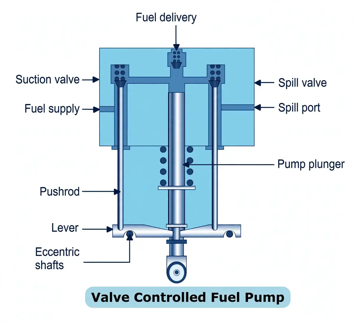
2. Sulzer RTA Series: Valve-Controlled Suction & Spill Mechanism
Sulzer rejected the moving-barrel approach in favor of a stationary barrel with dual eccentric-shaft-controlled poppet valves:
| Component | Mechanical Control | Operational Function |
|---|---|---|
| Suction Valve | Operated by a pushrod from a lower rocker arm driven by an eccentric VIT shaft. | Controls Start of Injection (Timing). As the plunger ascends, fuel is forced out through the open suction valve. When the rocker drops, the suction valve snaps shut under spring force. The instant the suction valve seats, high pressure builds and injection begins. Rotating the eccentric VIT shaft alters the rocker pivot height, advancing or retarding the moment of suction valve closure. |
| Spill Valve | Operated by a pushrod from a lower rocker arm driven by an eccentric Governor shaft. | Controls End of Injection (Quantity). As injection proceeds, the rising plunger lever pushes the spill valve open. The instant the spill valve lifts off its seat, high pressure collapses into the spill gallery, terminating injection. The governor rotates the spill eccentric shaft to modulate fuel quantity. |
Fuel Quality Setting (FQS) & Combustion Balancing
Marine diesel engines bunker residual heavy fuels with widely erratic combustion characteristics across global ports. Differences in refining (catalytic cracking vs visbreaking) produce fuels with severe ignition delay.
The Calculated Carbon Aromaticity Index (CCAI)
Unlike automotive diesel rated by Cetane Number, residual marine fuel ignition quality is quantified by the CCAI, calculated from density (ρ at 15°C in kg/m3) and kinematic viscosity (ν at 50°C in cSt):
Calculated Carbon Aromaticity Index (CCAI) Equation
CCAI = ρ − 140.7 · log10(log10(ν + 0.85)) − 80.6 − 483.5 · log10 T + 273.15 323.15
Normal fuels: CCAI 800–840 (short ignition delay). Poor ignition fuels: CCAI > 850–875 (long ignition delay, causing delayed peak pressure and severe afterburning).
The Fuel Quality Setting (FQS) Mechanism
When bunkering low-ignition-quality heavy fuel with high CCAI:
- Ignition delay causes fuel to accumulate in the cylinder during the delay period. When it finally lights off, combustion occurs late, dropping Pmax, raising exhaust temperatures, and increasing fuel consumption.
- To counteract this, the Chief Engineer uses the Fuel Quality Setting (FQS) mechanism situated on the engine side control stand.
- The FQS lever mechanically alters the baseline position of the VIT sensor beam. Adjusting the FQS knob by +1 to +3 index marks advances the start of fuel injection by 1° to 3° crank angle across ALL cylinders simultaneously. This restores Pmax to nominal design values without altering the automated load-dependent advance slope.
Individual vs Collective Cylinder Tuning
During routine watchkeeping, indicator cards are taken using electronic pressure analyzers (e.g., Doctor System or MAN CoCoS):
- Individual Cylinder Pmax Balancing: If one cylinder displays a Pmax deviation greater than ±3.0 bar from the engine average:
- Adjust the threaded turnbuckle linkage on the individual VIT rack position servo of that pump.
- Shortening or lengthening the turnbuckle shifts that specific pump barrel up or down, advancing or retarding that cylinder independently until all cylinders fire within ±1.5 to 2.5 bar.
- Collective Pmax Adjustment: If all cylinders uniformly read low or high due to ambient air temperature or fuel calorific value changes, adjust the collective adjustment screw on the position sensor unit.
Electronic Injection Shaping: MAN ME & WinGD RT-flex/X-Engines
In modern electronically controlled marine diesels (MAN ME and WinGD RT-flex / X-Engines), mechanical camshafts, fuel pump racks, moving barrels, and pneumatic VIT linkages have been completely eliminated.
Digital Cycle-by-Cycle Timing & Rate Shaping
Electronic engine management computers (ECUs) calculate the optimal start of injection, fuel volume, and injection pressure for every single stroke in real time based on engine load, RPM, scavenge air pressure, and ambient humidity:
- MAN ME / ME-C Architecture:
- The conventional camshaft jerk pump is replaced by a hydraulic fuel pressure booster powered by servo oil from the engine-specific hydraulic power supply; pressure depends on engine series.
- The FIVA (Fuel Injection & Valve Actuation) or ELFI (Electronic Fuel Injection) high-speed proportional spool valve controls servo oil flow to the booster piston.
- Start of injection (timing), duration (quantity), and booster pressure (atomization energy) are fully variable at any crank angle.
- WinGD RT-flex / X-Engines Architecture:
- Utilizes a high-pressure Common Rail delivering fuel oil at a steady 1,000 bar.
- Each cylinder features an Injection Control Unit (ICU) operated by electro-hydraulic fast-acting rail valves.
Advanced Rate-Shaping Modes
- "Boot" Shaped Injection: Initial fuel delivery starts at a gentle, restricted rate to initiate a smooth flame front before ramping up to maximum injection pressure. This avoids violent pressure spikes (dP/dθ), cutting combustion noise and mechanical shock.
- Pilot Pre-Injection: A micro-pulse of fuel is injected 5° to 10° ahead of the main charge to pre-heat the combustion chamber, dramatically cutting ignition delay for poor-quality bunkers.
- Twin / Staggered Injection: In multi-injector cylinder covers, individual fuel injectors are fired sequentially rather than simultaneously during low-load operation, concentrating heat and ensuring clean, smokeless combustion down to 10% engine load.
The NOx–SFOC Trade-off & IMO Tier II/III Compliance
Every marine propulsion engineer must understand the fundamental thermodynamic conflict between fuel efficiency and atmospheric emissions: the NOx–SFOC Trade-off.
The Zeldovich Thermal NOx Mechanism
Over 95% of NOx emitted by marine diesel engines is generated through the thermal Zeldovich mechanism, which is governed by peak in-cylinder temperature (Tpeak) and oxygen residence time:
- Advancing Injection Timing (Optimizing SFOC):
- Advancing timing causes fuel to burn earlier relative to TDC, forcing combustion into a smaller clearance volume.
- This raises Pmax and elevates peak flame temperatures above 1,600°C to 1,900°C.
- Benefit: Thermodynamic efficiency is maximized; SFOC drops by 3–6 g/kWh.
- Penalty: Thermal NOx generation accelerates exponentially, easily exceeding statutory IMO limits!
- Retarding Injection Timing (Suppressing NOx):
- Retarding timing delays combustion into the downward expansion stroke.
- Peak firing pressure drops and peak combustion temperature falls below the 1,400°C threshold where atmospheric nitrogen reacts with oxygen.
- Benefit: NOx emissions plunge by 20% to 35%, facilitating compliance with statutory Tier II/Tier III caps.
- Penalty: Late combustion increases Specific Fuel Oil Consumption by 2% to 4% and raises exhaust gas temperatures by 15°C to 30°C.
IMO NOx Tier Regulations Overview
| IMO Tier Standard | Implementation Year | Max NOx Limit (for n < 130 RPM) | Technical Compliance Strategy |
|---|---|---|---|
| Tier I | 2000 (Global) | 17.0 g/kWh | Basic fuel pump timing retard and slide-valve injector nozzles. |
| Tier II | 2011 (Global) | 14.4 g/kWh (~15% below Tier I) | Optimized bowl geometry, variable electronic timing, high-pressure injection, and Miller valve timing. |
| Tier III | 2016 (ECAs: Baltic, North Sea, North America) | 3.4 g/kWh (~80% below Tier I) | Cannot be achieved by timing alone on liquid fuel! Requires Exhaust Gas Recirculation (EGR), Selective Catalytic Reduction (SCR) with urea, or switching to LNG gas mode. |
Dual Operating Modes on Electronic Engines
Modern MAN ME and WinGD engines feature automated multi-mode software selectable via the Main Operating Panel (MOP):
- Fuel Economy Mode (High Seas / Open Ocean): Outside ECAs, the engine operates in Tier II fuel-optimized mode. Injection timing is advanced via VIT logic to maximize Pmax at part-load, burning the minimum possible fuel and slashing CO2.
- Low NOx Mode (ECA Entry): Upon approaching an ECA boundary, the engineer selects Low NOx Mode. The engine control system automatically retards injection timing, adjusts exhaust valve closing, and activates the EGR or SCR systems to guarantee strict Tier III compliance.
Calibration, Metrology & Troubleshooting Matrix
Proper calibration and maintenance of VIT mechanisms are vital. A misadjusted VIT linkage will either crack engine structural components from excessive firing pressure or waste hundreds of tons of fuel.
Sea Trial Calibration of the 85% MCR Breakpoint
- Warm-Up & Stabilization: Run the vessel in open sea under steady conditions until engine temperatures and pressures stabilize.
- Ramp to 85% MCR: Increase engine load to exactly 85% MCR (verified by shaft torsionmeter and fuel rack index).
- Verify Breakpoint Contact: Open the position sensor unit on the emergency stand. The sensor beam must just touch both mechanical stop supports simultaneously. If it does not, loosen locking clamp bolts and adjust the sensor arm until dual contact is established.
- Ramp to 100% MCR: Increase load to 100% MCR. Take indicator cards on all cylinders. Verify that Pmax does not exceed the engine nameplate limit. If Pmax rises above the 85% value, adjust the high-load retard stop screw.
- Rough Sea Stability Criterion: During sea trials in heavy swells, governor fuel rack fluctuations of ±2 index marks must NOT cause erratic oscillation of the VIT rack. If the VIT rack hunts violently, adjust the hydraulic damping throttle screw on the position sensor servo.
VIT Operational Troubleshooting Matrix
| Observed Fault | Probable Root Causes | Corrective Action |
|---|---|---|
| Single cylinder Pmax exceeds design limit (>+5 bar) |
|
Adjust individual VIT servo turnbuckle to lower pump barrel. Check fuel injector on test bench. If barrel is seized, overhaul pump during next port stay. |
| All cylinders Pmax low across 50%–85% load range |
|
Check control air pressure reducing station. Inspect position sensor valve seals. Advance Fuel Quality Setting (FQS) lever by +1 to +2 index marks. |
| Violent hunting of all VIT racks during sea passage |
|
Throttle the hydraulic damping needle valve on the sensor unit to stabilize pneumatic output. Replace worn spherical rod-end bearings on governor linkages. |
| High exhaust gas temperatures + drop in Pmax | VIT mechanism jammed in fully retarded position (pneumatic diaphragm ruptured or return spring broken). | Inspect position servo pneumatic actuators on all fuel pumps. Replace ruptured rubber diaphragms. Verify smooth manual movement of VIT racks. |
Found a mistake, or something unclear?
Report it in a few seconds — it goes straight to the editors.