

Marine Fuel Injection Pumps — Jerk Systems, Super-VIT Mechanisms & Common Rail Injection
Master marine fuel injection pumps: valve and helix jerk pumps, Super-VIT barrel shift, FQS heavy fuel adjustment, and electronic common-rail systems.
1. High-Pressure Metering Physics: Pressures, Dynamics & Cavitation
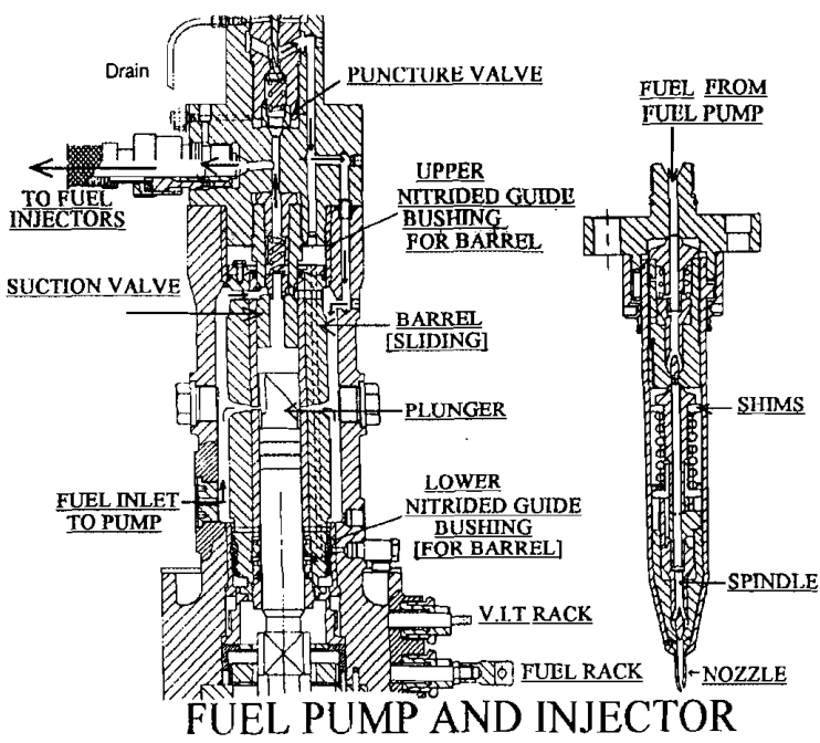
The fuel injection system is the thermodynamic heart of the marine diesel engine. In modern large two-stroke crosshead engines, the fuel pump must deliver heavy fuel oil (HFO) preheated to 130°C–150°C at pressures between 800 and 1,200 bar (up to 1,500 bar in modern common-rail installations) into a combustion chamber charged with scavenge air compressed to 35–45 bar.
This hydraulic pressure must be developed within milliseconds: at 100 RPM, one degree of crankshaft rotation elapses in just 1.67 milliseconds. A complete fuel injection event lasting 15° to 22° of crank angle occurs in approximately 25 to 37 milliseconds!
Acoustic Pressure Waves in Fuel Injection Lines
Liquid fuel oil is not incompressible under extreme dynamic pressures. The bulk modulus of elasticity of fuel oil (K ≈ 1.4 × 10⁹ Pa) causes the liquid column to behave as an elastic medium. When the pump plunger accelerates upward and closes the suction ports, it generates an acoustic compression wave that travels through the high-pressure pipe at the speed of sound in oil:
Acoustic Wave Speed in Fuel Lines
Where K is the fuel bulk modulus (~1.4 GPa) and ρ is the fuel density (~950 to 1,010 kg/m3). The resulting acoustic propagation velocity c is approximately 1,200 to 1,400 m/s.
This acoustic wave travels from the fuel pump delivery valve to the fuel injector nozzle. Upon reaching the closed needle valve, the wave reflects with doubled amplitude, lifting the needle against its spring. When injection terminates and the pump spills, a steep rarefaction (negative pressure) wave is initiated.
Cavitation Erosion & Delivery Valve Snubbers
When the pump plunger uncovers the spill port at the end of the effective stroke, fuel pressurized to 800+ bar rushes through the narrow spill passage into the low-pressure suction gallery (3 to 6 bar). This extreme pressure drop produces localized fluid velocities exceeding 300 m/s:
- The local static pressure falls below the vapor pressure of the hot fuel, causing spontaneous vaporization and the formation of millions of microscopic vapor cavities (bubbles).
- As the fluid decelerates in the suction gallery, static pressure recovers and the vapor cavities collapse violently. The microscopic implosions generate localized micro-jets with shock pressures exceeding 10,000 bar, gouging metal from the pump barrel and casing—a destructive phenomenon known as cavitation erosion.
- To protect the pump housing, manufacturers install replaceable, case-hardened steel spill deflector plugs directly opposite the spill ports to absorb the destructive shockwaves.
- Furthermore, the pump delivery valve is fitted with an anti-cavitation snubber valve (or constant-pressure retraction valve) that maintains a stable residual pressure (typically 30 to 50 bar) in the high-pressure pipe between injections, preventing the formation of cavitation voids in the fuel lines.
2. Valve-Controlled Jerk Pumps: Sulzer RD/RND Architecture
Before the universal adoption of helix-and-port pumps on slow-speed diesels, valve-controlled jerk pumps were standard equipment on Sulzer RD, RND, and classic Doxford opposed-piston engines. They remain a benchmark of mechanical robustness and are extensively examined in MEO oral boards.
Mechanical Construction & Working Cycle
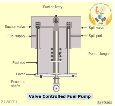
Unlike helix pumps, the plunger in a valve-controlled pump is a solid, symmetrical, precision-lapped cylinder with no scrolls, no cutouts, and no rotation. Fuel flow into and out of the pumping chamber is controlled by two separate poppet valves:
- Suction Valve: Controls fuel entry during the downward plunger stroke and dictates the start of injection.
- Spill Valve: Relieves pressure back to the suction line during the upward plunger stroke, dictating the end of injection.
The Operating Sequence
- Suction Stroke: As the cam roller descends into the base circle, the plunger moves downward under spring force. Fuel oil at booster pressure (6 to 8 bar) flows past the open suction valve into the pumping chamber.
- Start of Injection: As the cam rotates, the cam rise pushes the plunger upward. Initially, fuel is forced back through the open suction valve. At a predetermined crank angle, the suction valve pushrod (actuated by an eccentric rocker lever) allows the suction valve to seat. With both suction and spill valves closed, fuel is trapped, pressure skyrockets, and delivery begins through the discharge valve to the injectors.
- End of Injection (Spill): As the plunger continues upward, a second pushrod connected to the spill valve eccentric lever contacts the spill valve spindle, forcing it open. Pumping chamber pressure immediately collapses; the delivery valve snaps shut; remaining fuel spills through the open valve into the return manifold for the rest of the plunger stroke.
Independent Control of Quantity & Timing
| Control Function | Actuating Mechanism | Operational Effect |
|---|---|---|
| Fuel Quantity Metering | Spill Valve Eccentric Shaft connected directly to the governor output linkage. | Rotating the spill eccentric moves the fulcrum of the spill lever, causing the spill valve to open earlier (low load) or later (high load), varying the effective delivery stroke. |
| Injection Timing (VIT) | Suction Valve Eccentric Shaft connected to a manual or automated timing actuator. | Rotating the suction eccentric causes the suction valve to seat earlier (advancing start of injection) or later (retarding start of injection) without altering fuel quantity. |
Engineering Advantages & Maintenance
- Zero Plunger Side-Thrust: Because the plunger is completely symmetrical and does not rotate, it experiences purely axial loading, minimizing barrel scuffing and permitting long service lives even when burning abrasive, high-viscosity residual fuels.
- Tappet Clearance Adjustments: Tappet clearances between the pushrods and valve spindles are critical. Wear on valve seats causes valves to sink, altering timing and delivery quantity. Routine maintenance requires checking and resetting suction and spill valve clearances using feeler gauges to within ±0.05 mm.
3. Helix & Port-Controlled Jerk Pumps: Bosch / MAN B&W System
The helix-and-port pump (frequently referred to as the Bosch jerk pump) is the dominant mechanical injection pump on modern marine diesel engines. It eliminates external valve linkages by utilizing the motion and geometry of the plunger itself to open and close barrel ports.
Plunger & Barrel Metallurgy & Tolerances
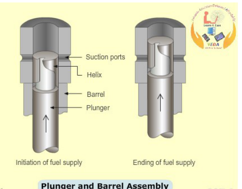
The plunger and barrel assembly represents the pinnacle of precision manufacturing in marine engineering:
- Material: High-grade alloy steel (e.g., chrome-molybdenum or nitrided alloy steel) heat-treated to a surface hardness of 60 to 65 HRC to resist abrasive catalytic fines (Al+Si particles) in heavy fuel oil. Modern high-pressure pumps apply diamond-like carbon (DLC) coatings to plungers to eliminate micro-scuffing.
- Radial Clearance: The diametral clearance between plunger and barrel is between 3 and 6 micrometers (μm). This mirror-finished fit is so tight that the plunger relies exclusively on the hydrodynamic lubricating film provided by the fuel oil itself. If fuel temperature exceeds 150°C (viscosity < 2 cSt) or drops below 100°C (thermal shock), the plunger can seize instantaneously!
- Matched Sets: Plunger and barrel are lapped together as a non-interchangeable matched pair. They must never be replaced separately.
The Four Phases of the Pumping Stroke
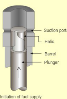
- Suction & Filling Phase: Plunger is at bottom dead center (BDC). Both the spill port and suction port in the barrel are fully uncovered. Fuel oil at 4 to 8 bar fills the barrel chamber above the plunger and the helical groove via the vertical slot.
- Pre-Stroke (Free Lift): The cam lifts the plunger upward. Fuel is initially expelled back out through the ports into the suction gallery. Injection does not occur until the plunger top edge fully covers the top edge of both barrel ports. This pre-stroke allows the cam follower to accelerate smoothly onto the steep velocity flank of the cam profile before compression begins.
- Effective Delivery Stroke: The instant the plunger top edge seals the barrel ports, fuel is trapped in the barrel. Hydraulic pressure escalates from 6 bar to over 300 bar within microseconds. The delivery valve lifts against its spring, and fuel discharges into the high-pressure pipe toward the fuel injectors. Delivery continues throughout the effective stroke.
- Spill Phase: As the plunger continues its upward travel, the lower helical (oblique) control edge uncovers the spill port. Fuel at 800+ bar rushes through the vertical slot and helical groove, venting through the spill port into the suction gallery. Pressure collapses instantaneously; the delivery valve snaps shut; and the plunger finishes its residual stroke to the cam peak with ports open.
Quantity Metering via Plunger Rotation
The lower end of the plunger is formed with cross-flanges (plunger foot) that engage slots in a control sleeve. A toothed pinion fixed to the control sleeve meshes with the longitudinal fuel control rack connected to the governor:
Effective Stroke Determination
Because the helical edge is sloped, rotating the plunger changes the vertical distance between the top edge (constant port closure point) and the point where the helix uncovers the spill port.
- Zero Delivery (Stop): The vertical slot in the plunger aligns directly with the spill port throughout the entire stroke. The chamber cannot build pressure; zero fuel is delivered.
- Part Load: The plunger is rotated so the helix uncovers the spill port early in the upward stroke, producing a short effective stroke.
- Full Load (100% MCR): The plunger is rotated so the deepest part of the helix faces the spill port. The port remains covered for the maximum possible lift, delivering the maximum fuel mass.
Helix Geometry Classifications
| Helix Design | Port Closure (Start) | Port Opening (End) | Operational Characteristics |
|---|---|---|---|
| Lower Helix (Standard) | Constant | Variable | Start of injection is fixed at a constant crank angle across all loads; end of injection varies with fuel rack position. Standard for basic mechanical engines. |
| Upper Helix | Variable | Constant | Start of injection advances automatically as load increases; end of injection remains constant. Rarely used alone. |
| Double (Upper & Lower) Helix | Variable | Variable | Start of injection advances at part load while end of injection retards, optimizing combustion pressure across a wide load band without external mechanisms. |
4. Variable Injection Timing (Super-VIT) & Fuel Quality Setting (FQS)
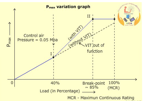
A conventional fixed-timing fuel pump is optimized for 100% Maximum Continuous Rating (MCR). At part loads (50% to 85% MCR)—where marine vessels operate 90% of their sea time—compression pressure is lower, and fixed injection timing causes combustion to occur late relative to TDC.
As a result, peak combustion pressure (Pmax) drops far below the structural design ceiling of the engine, penalizing thermal efficiency and increasing Specific Fuel Oil Consumption (SFOC). Variable Injection Timing (VIT) solves this problem by automatically advancing fuel injection timing at part load.
The Mechanical Super-VIT Mechanism
On MAN B&W MC-series engines, Super-VIT is achieved by physically shifting the pump barrel vertically relative to the plunger:
- The fuel pump barrel is split into an upper barrel and lower barrel, or the complete barrel is suspended in a threaded guide sleeve inside the pump housing.
- A secondary upper control rack (VIT rack) meshes with a toothed gear ring on the barrel adjustment sleeve.
- When the VIT rack moves:
- Lowering the Barrel: Moves the suction ports downward toward the approaching plunger. The plunger top edge covers the ports earlier in its upward stroke → Injection timing is ADVANCED.
- Raising the Barrel: Moves the suction ports upward away from the plunger. The plunger must travel further before closing the ports → Injection timing is RETARDED.
- The lower fuel rack continues to rotate the plunger to control fuel quantity independently. Thus, timing and quantity are adjusted completely independently with zero cross-interference!
The Super-VIT Three-Phase Load Profile
The VIT rack is actuated by a pneumatic positioner or electro-pneumatic positioner controlled by the engine governor according to fuel index (engine load):
| Engine Load Range | VIT Timing Behavior | Thermodynamic Objective & Pressure Behavior |
|---|---|---|
| Phase 1: 0% to ~40% MCR | Nominal Timing (No Advance) | Injection timing remains at baseline setting (approx. 2° to 3° BTDC). Ensures easy starting, stable low-speed maneuvering, and prevents excessive pressure rise rates during light load. |
| Phase 2: 40% to 85% MCR | Steep Linear Advance (+3° to +5° CA) | As load increases, the VIT rack pushes the barrel downward, advancing injection. This forces peak combustion pressure (Pmax) to climb steeply until it hits the 100% design plateau (e.g., 140 bar on MC, 180–210 bar on modern designs) at 85% MCR! Thermal efficiency is maximized, saving 3 to 6 g/kWh of fuel across the entire cruising range. |
| Phase 3: 85% to 100% MCR | Controlled Retardation | Above 85% MCR, scavenge air density and massive fuel charges would drive Pmax dangerously above structural limits. The VIT mechanism automatically retards injection back toward nominal, holding Pmax flat along its horizontal design plateau up to full 100% MCR. |
Fuel Quality Setting (FQS)
Marine residual heavy fuel oils vary wildly in ignition quality, quantified by the Calculated Carbon Aromaticity Index (CCAI). High-CCAI fuels (> 850) exhibit prolonged ignition delay periods: fuel accumulates in the cylinder before ignition, causing delayed combustion, dropping Pmax, elevating exhaust temperatures, and increasing SFOC.
The Fuel Quality Setting (FQS) mechanism is a manual micrometer adjustment built into the Super-VIT linkage:
- An engineer turns the knurled FQS knob, which mechanically shifts the baseline datum of the VIT linkage across all cylinder fuel pumps simultaneously by ±1° to 3° crank angle.
- When burning poor-ignition-quality fuel, the engineer advances the FQS index (+1 to +3 marks), advancing start of injection to compensate for ignition delay and restoring Pmax to nominal design limits without altering the automated load-dependent advance slope.
- Balancing Rule: Individual cylinder pumps are first balanced to within ±3.0 bar Pmax using individual barrel eccentric stops; then the overall engine is trimmed using the FQS knob based on daily indicator card analysis.
5. Common Rail Injection Systems: MAN ME & WinGD RT-flex/X-DF
The introduction of electronically controlled marine two-stroke diesel engines—MAN B&W ME-series and WinGD RT-flex / X-DF series—eliminated the mechanical camshaft entirely. In place of heavy chain drives, cams, roller guides, reversing servomotors, and mechanical jerk pumps, these engines utilize Common Rail high-pressure accumulator systems.
MAN ME Electro-Hydraulic Injection Architecture
The MAN ME system utilizes an integrated hydraulic power supply (HPS) and electronic fuel injection units:
- Hydraulic Power Supply (HPS): Engine-driven axial piston pumps pressurize system lubricating oil to 200 to 300 bar, feeding a continuous high-pressure hydraulic oil rail.
- Fuel Oil Pressure Booster (FOPB): Each cylinder has an individual electronic fuel injection booster. The booster comprises a double-acting hydraulic piston driving a smaller fuel plunger (ratio ~3:1), multiplying 300-bar hydraulic oil pressure into 900 to 1,200+ bar fuel injection pressure.
- Proportional Electronic Valve (ELFI / FIVA): An ultra-fast proportional electro-hydraulic spool valve (FIVA - Fuel Injection and Valve Actuation) receives digital commands from the Cylinder Control Unit (CCU). The valve ports hydraulic oil to the booster piston with microsecond accuracy.
WinGD RT-flex Common Rail Architecture
The WinGD (formerly Sulzer) RT-flex system utilizes a true high-pressure common rail for fuel oil:
- High-Pressure Fuel Supply Pumps: Swashplate axial piston pumps driven from the crankshaft pump heavy fuel oil directly into a continuous heated fuel manifold rail maintained at 1,000 bar along the engine top platform.
- Electro-Hydraulic Rail Valves: High-speed bistable solenoid valves control fuel admission from the rail directly to the spring-loaded fuel injectors via hydraulic control pistons.
Thermodynamic & Operational Advantages Over Mechanical Jerk Pumps
| Operational Capability | Mechanical Jerk Pump (MC) | Electronic Common Rail (ME / RT-flex) |
|---|---|---|
| Injection Pressure at Low RPM | Very Low (< 250 bar). Cam velocity is slow; droplet size is large; poor atomization causes heavy smoking at dead slow. | Maximum Full Pressure (1,000+ bar). Rail pressure is independent of engine speed, providing ultra-fine atomization and smokeless operation down to 10% dead slow RPM! |
| Injection Rate Shaping | Fixed by cam profile. Rapid initial pressure spike causes combustion knock and high NOx. | Fully Programmable. "Boot-shaped" initial delivery ramps fuel gently to initiate a smooth flame front before ramping to peak pressure, reducing combustion noise, vibration, and NOx emissions. |
| Multiple Injections per Cycle | Impossible. Only one injection event per working stroke. | Standard Feature. Capable of pilot injection (pre-injection for quiet ignition) and post-injection (soot reduction or SCR temperature management). |
| Individual Cylinder Balancing | Manual adjustment of fuel rack turnbuckles and VIT barrel stops during port stops. | Real-Time Closed-Loop Auto-Balancing. CCU continuously monitors cylinder MIP and Pmax, auto-trimming timing (±0.1° CA) and fuel volume per cylinder while running. |
| Engine Reversing | Requires mechanical reversing servomotors to axially shift camshaft or reposition cam rollers. | Instantaneous Software Commutation. The ECU simply shifts the electronic injection firing sequence in software; zero mechanical repositioning required. |
6. MEO Class 1 & Class 2 Examination Technical Scenarios & Oral Assessment
Maritime Examiner Oral Assessment Standards
Questions on fuel injection pumps, Super-VIT operation, FQS calibration, and common-rail systems are among the most frequently asked in MEO Class 4, Class 2, and Class 1 examinations. Surveyors expect candidates to draw and explain plunger helixes, barrel shift mechanisms, and cavitation erosion defenses from first engineering principles.
Q1: Explain the step-by-step operating cycle of a Bosch-type helix jerk fuel pump. How is the effective stroke varied by moving the fuel control rack?
Model Engineering Answer:
The Bosch helix pump operates across four distinct phases:
- Suction & Filling: When the plunger is at BDC, both the suction and spill ports in the barrel are uncovered. Fuel oil at booster pressure (4 to 8 bar) fills the barrel pumping chamber and the helical groove via the vertical slot.
- Pre-Stroke: As the cam lifts the plunger, fuel is initially displaced back out through the ports into the suction gallery. Injection does not begin until the plunger top edge fully covers both barrel ports. This pre-stroke allows the cam follower to accelerate to maximum velocity before compression commences.
- Effective Delivery Stroke: Once the top edge covers the ports, fuel is trapped in the barrel. Hydraulic pressure escalates past the injector opening pressure (300+ bar), lifting the delivery valve against its spring and injecting fuel into the cylinder. Pumping continues as long as the barrel ports remain covered.
- Spill Phase: Pumping terminates the instant the plunger's lower helical (oblique) control edge uncovers the spill port. Fuel at 800+ bar rushes through the vertical slot and helix, venting through the spill port into the suction gallery. Pressure collapses instantaneously, the delivery valve snaps shut, and the plunger completes its residual upward stroke with ports open.
Rack Metering: The fuel control rack meshes with a pinion sleeve that engages the plunger foot via driving dogs. Moving the rack rotates the plunger inside the barrel. Because the spill edge is helical, rotating the plunger changes the vertical distance between the top cutoff edge and the spill uncovering point—lengthening the effective stroke for high loads and shortening it for low loads. In the STOP position, the vertical slot faces the spill port continuously, preventing pressure buildup.
Q2: Describe the mechanical operation of the MAN B&W Super-VIT mechanism. How does shifting the pump barrel alter injection timing without affecting fuel quantity?
Model Engineering Answer:
On MAN B&W MC engines, Super-VIT adjusts injection timing by physically raising or lowering the pump barrel relative to the plunger:
- The barrel is fitted inside an externally threaded guide sleeve that meshes with an upper control rack (VIT rack) driven by a pneumatic or electro-pneumatic positioner controlled by the governor.
- When the VIT rack moves, it rotates the threaded sleeve, shifting the barrel vertically:
- Lowering the Barrel: Moves the suction ports closer to the plunger at BDC. The plunger top edge closes the ports earlier in the cam lift stroke → Injection timing is ADVANCED.
- Raising the Barrel: Moves the suction ports higher. The plunger must travel further before closing the ports → Injection timing is RETARDED.
- Independence: Fuel quantity is controlled exclusively by the lower fuel rack, which rotates the plunger to dictate when the lower helix uncovers the spill port. Because vertical movement of the barrel changes both the port closure point and the spill point by the exact same vertical distance, the net distance (effective stroke) remains identical. Thus, timing is modified with zero interference to metered fuel volume.
Q3: What is the purpose of the Fuel Quality Setting (FQS), and how does an engineer utilize indicator card data to adjust it when burning poor-quality heavy fuel oil?
Model Engineering Answer:
Purpose: The FQS mechanism compensates for variable fuel ignition quality (high CCAI / poor ignition delay). Low-ignition-quality residual fuels experience prolonged ignition delay: fuel droplets take longer to vaporize and auto-ignite, causing late combustion, lower peak pressure (Pmax), high exhaust gas temperatures, and increased SFOC.
FQS Adjustment Procedure:
- After bunkering and switching to a new fuel, bring the engine to steady cruising load (> 75% MCR).
- Take a complete set of indicator diagrams (P-V power cards and P-θ draw cards) on all cylinders. Record individual cylinder compression pressures (Pcomp), peak firing pressures (Pmax), and exhaust temperatures.
- Calculate the average Pmax across all units and compare it against the engine manufacturer's shop trial baseline curve for that running load.
- If average Pmax has dropped by 4 to 8 bar below the nominal baseline due to prolonged ignition delay, adjust the FQS knurled knob on the VIT linkage to advance timing by +1 to +2 index marks.
- The FQS shifts the baseline datum of the VIT linkage across all cylinder fuel pumps simultaneously, advancing injection by 1° to 2° crank angle.
- Retake indicator cards to verify that average Pmax has returned to its nominal design limit without exceeding the maximum permissible cylinder pressure, and confirm that exhaust gas temperatures have normalized.
Q4: What causes cavitation erosion in fuel injection pump barrels and spill ports, and what design features are incorporated to prevent failure?
Model Engineering Answer:
Cause: At the end of the effective delivery stroke, the plunger helix uncovers the spill port while fuel chamber pressure is at 800+ bar. Fuel discharges into the 4-to-6-bar suction gallery at velocities exceeding 300 m/s. The extreme local pressure drop falls below the vapor pressure of the 140°C fuel oil, creating millions of microscopic vapor cavities. As the fluid enters the lower-velocity suction gallery, pressure recovers and the vapor cavities implode violently, generating micro-jets with shock pressures exceeding 10,000 bar that erode and crater the metal surfaces of the barrel, plunger, and pump casing.
Design Defenses:
- Hardened Spill Deflector Plugs: Case-hardened sacrificial steel plugs are screwed into the pump casing directly opposite each spill port to absorb the direct impact of the high-velocity fuel jet, protecting the pump body casting.
- Anti-Cavitation / Snubber Delivery Valves: Delivery valves incorporate calibrated non-return throttle discs or constant-pressure retraction pistons that maintain a stable residual pressure (30 to 50 bar) in the high-pressure line between injections, suppressing negative rarefaction waves that cause cavitation in fuel lines.
- Ceramic / DLC Coatings: Modern fuel plungers apply diamond-like carbon (DLC) coatings to the helical edge zone to resist erosive pitting.
Q5: Contrast the operating characteristics of a conventional mechanical jerk pump system with a modern electronic Common Rail system (MAN ME or WinGD RT-flex) during low-speed maneuvering.
Model Engineering Answer:
During low-speed maneuvering (Dead Slow Ahead/Astern):
- Mechanical Jerk Pump (MC Engine): Fuel injection pressure is directly dependent on camshaft rotational velocity. At 20 to 30 RPM, plunger lift velocity is very slow, generating poor hydraulic injection pressure (< 250 bar). Fuel sprays out of injectors in coarse droplets rather than a fine atomized mist. The large droplets burn sluggishly with high soot formation, producing heavy black smoke, fouling exhaust passages and turbocharger nozzles, and setting a minimum stable running speed limit of approximately 25 to 30 RPM.
- Electronic Common Rail (ME / RT-flex): Injection pressure is completely decoupled from engine speed. The high-pressure hydraulic rail (ME) or fuel rail (RT-flex) maintains full 1,000+ bar injection pressure even when the engine is rotating at just 8 to 12 RPM. Injected fuel is atomized into an ultra-fine microscopic mist, achieving clean, smokeless combustion. In addition, the electronic control system can execute pilot injection (pre-injection) and cylinder cut-out strategies, enabling steady, reliable dead-slow operation down to 10 to 12 RPM without smoke or spark plug fouling.
Found a mistake, or something unclear?
Report it in a few seconds — it goes straight to the editors.