

Dual-Fuel Marine Diesel Engines: MAN ME-GI vs WinGD X-DF
Master marine dual-fuel engines: ME-GI vs X-DF thermodynamic cycles, pilot injection, methane slip, GVU, double-walled piping, and IGF Code compliance.
Thermodynamic Principles: High-Pressure Diesel vs Low-Pressure Otto Cycle
The decarbonization of global shipping and the enforcement of the IMO 2020 sulfur cap and IMO Tier III nitrogen oxide (NOx) emission limits in Emission Control Areas (ECAs) have made Liquefied Natural Gas (LNG) and future low-flashpoint fuels (such as biomethane and synthetic e-methane) the preeminent alternative fuels for large commercial vessels.
In the large two-stroke propulsion market, two fundamentally different thermodynamic and mechanical philosophies have emerged:
- MAN Energy Solutions ME-GI (Gas Injection): Employs a High-Pressure Gas Injection Diesel Cycle (gas admitted at approximately 300 bar near Top Dead Center).
- WinGD X-DF (eXtreme Dual Fuel): Employs a Low-Pressure Lean-Burn Otto Cycle (gas admitted at approximately 10 to 16 bar mid-stroke during the compression stroke).
1. MAN ME-GI: High-Pressure Diesel Cycle Architecture
The ME-GI engine operates strictly according to the classical internal combustion Diesel cycle:
- Air Compression Only: Pure scavenge air is drawn into the cylinder and compressed through a high compression ratio (typically 18:1 to 21:1). As the piston ascends, air pressure rises to 140–160 bar and in-cylinder temperature exceeds 650°C to 700°C. No fuel gas is present in the cylinder during the compression stroke.
- Micro-Pilot Fuel Ignition: Just prior to Top Dead Center (TDC), approximately 2° to 3° before gas admission, a small quantity of pilot marine gas oil (MGO) or low-sulfur fuel oil—typically 1.5% to 5% of total fuel energy—is injected into the hot compressed air. The pilot oil atomizes and self-ignites via compression ignition.
- Late High-Pressure Gas Injection: Immediately following pilot ignition, natural gas (methane, CH4) is injected directly into the burning pilot flame at a staggering pressure of 250 to 315 bar. The gas ignites instantaneously on contact with the flame front and burns as a turbulent diffusion flame.
- Zero Knock & Superior Thermal Efficiency: Because the fuel gas is injected directly into the flame near TDC and burns progressively as it enters, the fuel-air charge is never premixed in the cylinder space. Consequently, engine knocking (end-gas detonation) is physically impossible. The engine maintains identical compression ratios, identical peak combustion pressures (Pmax up to 210 bar), and the exact same outstanding thermal efficiency (approaching 54% to 55%) as a conventional heavy-fuel diesel engine across all ambient temperatures and loads.
2. WinGD X-DF: Low-Pressure Lean-Burn Otto Cycle Architecture
The WinGD X-DF engine (and MAN's newer ME-GA design) operates on the premixed lean-burn Otto cycle:
- Mid-Stroke Gas Admission: Shortly after the piston sweeps past bottom dead center and the exhaust valve closes, natural gas is admitted into the cylinder at low pressure (10 to 16 bar) through two electronically controlled Gas Admission Valves (GAV) mounted diametrically opposite in the cylinder liner wall.
- Lean-Burn Homogeneous Mixing: As the piston travels upward toward TDC, the gas mixes intimately with the scavenge air, creating an ultra-lean homogeneous fuel-air mixture. The excess air ratio (lambda, λ) is tightly maintained between 2.0 and 2.2 (more than double the stoichiometric air requirement).
- Micro-Pilot Pre-Chamber Ignition: Near TDC, a tiny micro-pilot fuel charge (representing less than 1% of total fuel energy) is injected into an ignition pre-chamber or directly into the bowl. High-energy flame jets shoot outward from the pilot nozzle into the main combustion space, igniting the lean homogeneous gas-air charge.
- Low Flame Temperature & Low Pressure Dynamics: The presence of massive excess air acts as a thermal sink. The entire charge burns uniformly with a low peak combustion temperature (below 1,400°C), drastically curtailing the thermal fixation of atmospheric nitrogen.
Emissions, Methane Slip & IMO Tier III Compliance
The divergence between the high-pressure Diesel cycle and low-pressure Otto cycle creates profound differences in environmental compliance, aftertreatment requirements, and greenhouse gas (GHG) life-cycle accounting.
1. Nitrogen Oxide (NOx) Formation & Tier III Compliance
The generation of thermal NOx in internal combustion engines is governed by the extended Zeldovich mechanism, where the rate of formation escalates exponentially at combustion temperatures exceeding 1,400°C to 1,500°C:
Thermal NOx Formation (Zeldovich Mechanism)
O + N2 ⇄ NO + N
N + O2 ⇄ NO + O
Reaction rate constant k ∝ exp(−Ea / (R · T)); formation rates surge at T > 1,600 K.
- WinGD X-DF (Inherent Tier III Compliance): Because combustion occurs in a lean-burn premixed charge (λ ≈ 2.1), peak localized flame temperatures never exceed 1,350°C. Consequently, thermal NOx formation is suppressed by over 80% to 85% compared to standard diesel operation. The engine complies effortlessly with IMO Tier III limits (approx. 2.0 to 3.4 g/kWh) in gas mode WITHOUT any exhaust gas aftertreatment (no SCR catalyst and no EGR system).
- MAN ME-GI (Requires Aftertreatment for Tier III): In the ME-GI engine, gas is injected directly into a high-temperature diffusion flame, and localized peak temperatures exceed 1,800°C to 2,000°C. While NOx emissions are reduced by 20% to 30% relative to heavy fuel oil due to clean gaseous combustion, they still exceed the strict IMO Tier III ECA ceiling. Therefore, an ME-GI engine operating inside an ECA must utilize either:
- High-pressure or low-pressure Selective Catalytic Reduction (SCR) with urea injection, or
- An integrated Exhaust Gas Recirculation (EGR) system to reduce oxygen concentration and lower peak flame temperatures.
2. The Methane Slip Challenge
While burning natural gas slashes carbon dioxide (CO2) by 20% to 25% (due to methane's high hydrogen-to-carbon ratio: CH4 = 4:1 vs diesel oil ~1.8:1), unburnt methane emissions (methane slip) represent a significant global warming risk. Methane possesses a 100-year Global Warming Potential (GWP) 28 to 36 times higher than CO2 (and over 80 times higher over a 20-year horizon).
| Parameter | MAN ME-GI (High-Pressure Diesel) | WinGD X-DF / MAN ME-GA (Low-Pressure Otto) |
|---|---|---|
| Methane Slip Value | 0.2 to 0.4 g/kWh (Negligible / Near Zero) | 1.5 to 2.5 g/kWh (Baseline X-DF) / <1.0 g/kWh (X-DF2.0 with iCER) |
| Physical Origin of Slip | Gas is injected when the exhaust valve is closed and immediately consumed by the active diffusion flame. | Piston ring pack crevice volumes, uniflow scavenge port overlap, and cold liner wall flame quenching. |
| GHG Benefit vs Diesel | Full 22% to 26% well-to-wake GHG reduction. | 10% to 15% net GHG reduction (reduced by methane warming penalty unless mitigated by iCER). |
Methane Slip Mitigation: WinGD iCER & MAN ME-GA EGR
To conquer the methane slip penalty in low-pressure engines, WinGD introduced iCER (intelligent Control by Exhaust Recycling):
- A fraction of the exhaust gas (up to 30–50%) is drawn off downstream of the turbocharger, cooled and washed in an on-engine scrubber tower, and routed back into the compressor inlet.
- The inert CO2 and water vapor replace a portion of the combustion air, increasing the specific heat capacity (Cp) of the in-cylinder charge.
- This dramatically enhances combustion stability, eliminates knock risk, and cuts methane slip by up to 50% (bringing emissions down below 1.0–1.2 g/kWh) while slashing fuel consumption by 3% in gas mode!
Engine Construction & Fuel Injection Hardware
The mechanical execution of dual-fuel injection represents the pinnacle of high-pressure fluid engineering. The hardware must guarantee absolute separation between combustible gas, high-pressure fuel oil, and engine lube oil circuits under all operating conditions.
1. MAN ME-GI: High-Pressure Fuel Booster & Injection Valves
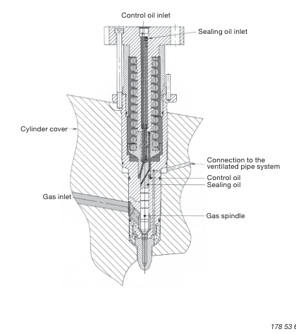
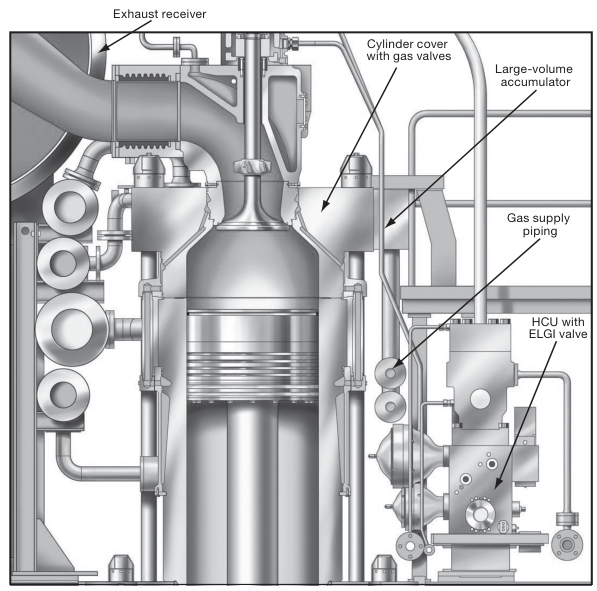
The ME-GI cylinder cover houses conventional fuel oil injectors alongside two or three dedicated High-Pressure Gas Injection Valves (ELGI / FBIV):
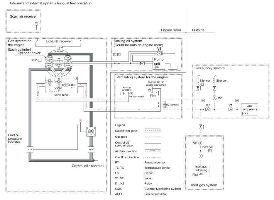
- Gas Supply Pressure: 300 bar gas is supplied via double-walled high-pressure pipes to the cylinder cover gas block.
- Hydraulic Sealing Oil System: The absolute cornerstone of ME-GI safety! If 300 bar gas were to leak past the gas valve spindle clearance, combustible gas would enter the engine control oil circuit or cylinder cover cavities. To make leakage physically impossible, an independent sealing oil system supplies system lube oil at 330 to 350 bar (strictly maintained at 30 to 50 bar ABOVE the gas pressure) to sealing grooves on the gas spindle. Any microscopic fluid migration is forced inward (clean sealing oil migrates into the gas path, never the reverse!).
- Gas Valve Actuation: The gas spindle needle is held closed by a heavy spring. High-pressure control oil from the FIVA (Fuel Injection & Valve Actuation) unit drives a hydraulic piston that lifts the gas needle, permitting supersonic gas injection into the bowl for a precise angular window (typically 15° to 30° crank angle).
- Window Valve Safety Function: A fast-acting "window valve" in the gas supply block shuts off gas flow to any individual cylinder within 20 milliseconds if the electronic control system detects that a gas injection needle has jammed open.
2. WinGD X-DF: Gas Admission Valves (GAV)
Because X-DF operates at low pressure, the injection hardware is situated in the cylinder liner rather than the cylinder cover:
- Cylinder Liner Mid-Stroke Admission: Two Gas Admission Valves (GAV) are installed on opposite sides of the upper cylinder liner, positioned below the top ring reversal zone but above the scavenge ports.
- Electronic Pilot Solenoid Actuation: When triggered by the engine control system (UNIC / WECS-9520), hydraulic servo oil or electronic solenoids actuate the GAV poppet valve. Natural gas at 10 to 16 bar enters the cylinder through specially contoured diffuser nozzles designed to promote toroidal swirl and thorough premixing with scavenge air.
- Micro-Pilot Injector: Situated centrally in the cylinder cover, a dedicated rail-fed micro-pilot injector delivers tiny, precisely metered fuel sprays (less than 1% MCR fuel) to trigger ignition at TDC.
- Closed-Loop Cylinder Balancing (Knock Sensors): High-frequency piezoelectric pressure transducers installed in every cylinder cover measure cylinder pressure (Pcyl) at 0.1° crank angle resolution. Advanced software algorithms detect the onset of high-frequency pressure oscillations characteristic of engine knock, automatically trimming individual cylinder gas admission duration in real time.
Fuel Gas Supply System (FGSS) & Gas Valve Unit (GVU)
The Fuel Gas Supply System (FGSS) processes cryogenic LNG from the ship's fuel tanks (−162°C, 1 to 4 bar) and transforms it into superheated natural gas delivered to the engine at precise pressures, temperatures, and cleanliness standards.
Comparison of FGSS Complexity
- High-Pressure FGSS (for ME-GI): Requires cryogenic high-pressure reciprocating plunger pumps submerged in or adjacent to the LNG fuel tank. These pumps compress liquid LNG to 300–320 bar, followed by a high-pressure printed circuit heat exchanger (PCHE) using hot glycol-water to vaporize the LNG into gas at +45°C. High capital cost and power consumption (~2% to 3% of engine power for pumping).
- Low-Pressure FGSS (for X-DF): Liquid LNG is delivered by a simple low-pressure centrifugal booster pump at 12 to 16 bar to a low-pressure shell-and-tube or plate vaporizer. Extremely simple, safe, low maintenance, and low electrical power demand (~0.2% of engine power).
The Gas Valve Unit (GVU) Architecture
The GVU acts as the safety gatekeeper between the engine room and the engine gas manifold. Its primary safety functions are:
- Gas Pressure Regulation: Modulates gas supply pressure accurately according to engine load requirements.
- Double Block and Bleed: Consists of two fail-safe, spring-loaded shut-off block valves (B1 and B2) with an automatic venting valve between them. In the event of an emergency shutdown (ESD) or gas trip, B1 and B2 slam shut in less than 25 milliseconds under spring force, while the intermediate vent valve instantly springs open, venting all trapped gas safely up the mast to atmosphere. This guarantees that gas can never leak past the seals into the engine room during shutdown!
- Automated Leak Testing: Before every start-up in gas mode, the GVU executes an automated sequence of pressure-hold tests: pressurizing between B1 and B2, holding pressure for 30 seconds to confirm zero seal decay, and venting before opening to the engine.
Double-Walled Ventilated Piping Regulations
The IGF Code dictates that inside machinery spaces, all fuel gas pipes must be of double-walled construction:
- Construction: A high-integrity stainless steel inner gas pipe is enclosed coaxially within a robust outer steel duct capable of withstanding the full design pressure of the gas line.
- Continuous Mechanical Ventilation: The annular space between the inner pipe and outer casing is continuously swept by mechanical exhaust extraction fans at a rate of at least 30 air changes per hour. The air pressure inside the annular space is maintained strictly negative (under-pressure relative to the engine room).
- Gas Detection Sensors: Hydrocarbon gas sniffing sensors (infrared optical or catalytic) sample the extraction exhaust duct continuously:
- At 20% Lower Explosive Limit (LEL): Audible and visual pre-alarms sound on bridge and ECR.
- At 40% LEL: The safety system triggers an immediate, automatic Gas Trip (ESD Level 1): GVU block valves slam shut, vent valve opens, and the engine automatically trips to 100% fuel oil mode without load loss.
Operational Modes, Fuel Changeover & Knock Prevention
One of the supreme engineering triumphs of modern dual-fuel engines is their ability to perform instantaneous, seamless transfers between gas and diesel fuel without any interruption to ship propulsion or electrical power.
Engine Operating Modes
- Dual Fuel Mode (Gas Mode): Natural gas provides 95% to 99% of combustion energy. Pilot fuel oil represents 1% (X-DF) to 5% (ME-GI) to control ignition timing.
- Diesel Fuel Oil Mode: The engine operates 100% on conventional marine gas oil (MGO) or heavy fuel oil (VLSFO). The gas system is completely isolated and purged with nitrogen. Performance, power, and thermal efficiency are identical to a conventional diesel engine.
- Specified Gas / Mixed Fuel Mode: On LNG carriers, the volume of natural boil-off gas (NBOG) varies with sea temperature and weather. In Mixed Mode, the engine burns 100% of available boil-off gas, while the electronic control system dynamically injects the exact remaining energy deficit in fuel oil to maintain requested propeller RPM.
Seamless On-Load Fuel Changeover
- Gas-to-Diesel Trip (Instantaneous < 1 Second): If a gas fault, GVU trip, or blackout condition occurs, the engine control system instantly transfers 100% of the fuel load to the fuel oil injection valves within a single engine revolution. Propeller RPM and ship speed remain entirely unaffected.
- Diesel-to-Gas Transfer (Controlled Ramp-Up 1–3 Minutes): When the Chief Engineer selects gas mode on the Main Operating Panel (MOP):
- The GVU completes automated pressure and leak testing.
- Double block valves open, admitting gas to the engine manifold.
- Gas injection begins at 10% load, while fuel oil injection is progressively throttled back over 60 to 180 seconds.
- Closed-loop combustion controllers monitor individual cylinder Pmax and knock sensor waveforms, continuously optimizing injection timing as the fuel ratio shifts.
Combustion Abnormalities in Otto Cycle Engines: Knock & Misfire
Because the WinGD X-DF operates with a premixed fuel-air charge, it is vulnerable to two opposing combustion boundaries:
- Engine Knock (Detonation): If the end-gas (unburnt fuel-air mixture in the outer perimeter) reaches its auto-ignition temperature before the flame front arrives, the entire end-gas detonates instantaneously. This creates violent localized supersonic pressure shockwaves (>200–250 bar) that can destroy piston rings, crown rims, and cylinder covers within minutes.
- Anti-Knock Controller: Piezoelectric knock sensors detect high-frequency pressure oscillations (5 to 8 kHz). If knock is detected, the engine control system instantly retards pilot injection timing, reduces gas admission duration for that individual cylinder, and enriches fuel oil to suppress detonation.
- Misfire (Lean Limit): If the mixture is excessively lean (λ > 2.3), the flame fails to propagate across the cylinder, causing unburnt gas to discharge into the exhaust manifold, triggering turbocharger backfires and high methane slip.
IGF Code Protocols, Nitrogen Inerting & Troubleshooting Matrix
The design and operation of all gas-fueled commercial vessels are strictly governed by the International Code of Safety for Ships Using Gases or Other Low-Flashpoint Fuels (IGF Code, MSC.391(95)).
Core Safety Mandates of the IGF Code
- Double Barrier Principle: Gas fuel piping must never rely on a single metal wall to contain gas within machinery spaces. Any primary barrier leak must be safely retained within the secondary ventilated barrier.
- Hazardous Area Classification:
- Zone 0: Areas where explosive gas is present continuously (inside LNG fuel tanks and pipe bores).
- Zone 1: Areas where an explosive atmosphere is likely during normal service (tank connection spaces, GVU enclosures). All electrical equipment must be explosion-proof (Ex-d / Ex-ia).
- Zone 2: Areas where an explosive atmosphere is not likely, but may occur during abnormal leaks (open deck surrounding tank vents, bunker manifold).
- Emergency Shutdown (ESD) Hierarchy:
- ESD Level 1 (Gas Trip): Closes GVU block valves, vents gas manifold to mast, switches engine to diesel oil without stopping propulsion.
- ESD Level 2 (Total Gas Plant Shutdown): Trips all FGSS cryogenic pumps, closes tank emergency shut-off valves, inerts piping with N2.
Nitrogen Purging & Inerting Protocol
Hydrocarbon gas must never come into contact with air inside pipelines. Before admitting gas into any component, or before opening equipment for maintenance, a strict 3-step purging cycle is executed using 99.5% pure nitrogen generated by shipboard N2 membrane generators:
The IGF Explosive Triangle Purging Rule
- AIR (21% O2).
- NITROGEN PURGE (O2 < 1%).
- METHANE GAS (CH4).
Warning: Never introduce gas into air, and never introduce air into gas! An intermediate N2 inert blanket is mandatory to avoid crossing the flammability envelope (5% to 15% CH4 in air).
Dual-Fuel Operational Troubleshooting Matrix
| Observed Alarm / Fault | Probable Root Causes | Immediate Corrective Action |
|---|---|---|
| Double-wall pipe gas leak alarm (20% LEL) |
|
Verify annular ventilation fan operation. Locate leaking pipe spool using handheld intrinsically safe sniffer. If leak reaches 40% LEL, confirm automatic gas trip to diesel mode and purge gas line with N2. |
| ME-GI Sealing Oil Pressure Low Alarm |
|
Immediate gas trip! Operating without sealing oil pressure allows 300 bar gas to contaminate the engine lube oil system. Check sealing oil differential pressure transmitter (must remain >30 bar above gas). |
| Persistent cylinder knock alarm on single unit (X-DF) |
|
Reduce engine load. Check scavenge cooler performance. If knock persists, engine control automatically cuts gas to that unit, running it on diesel while other cylinders continue in gas mode. Overhaul defective GAV during next stop. |
| GVU fails automated pre-start leak test |
|
Inert GVU with nitrogen. Open inspection cover and clean valve seats. Cycle valves manually using pneumatic test buttons. Re-run automated leak sequence. |
Standards & sources referenced
- IGF Code: Safety requirements for ships using gases or other low-flashpoint fuels.
- Conventions index
Found a mistake, or something unclear?
Report it in a few seconds — it goes straight to the editors.