
LSA Chapter 3: Line Throwing, EEBD & SCABA
General LSA — the line throwing apparatus, the emergency escape breathing device and the self-contained breathing apparatus — with the SOLAS figures surveyors test.
Key Principles at a Glance 7 points
- The line throwing apparatus comprises 4 projectiles each throwing at least 230 m in calm weather with 4 lines of at least 2 kN breaking strength, fired as a yellow cylinder at 45 degrees with the wind from the bridge after removing the safety pin.
- Pistol-fired rockets stow line, rockets and ignition means together in a weather-protecting container, while integral rocket-and-line assemblies sit in a water-resistant casing; the high-tension spring fires the line out of the cylinder when the lever is pressed.
- EEBDs on a cargo ship: minimum 2 in the accommodation plus 1 spare, 1 in the engine room, 1 in the workshop and 1 on each deck or platform; each gives at least 10 minutes of escape air from a 2.5-litre demand-valve set with hood, alarm and pressure indicator.
- The EEBD must never be used for firefighting, in oxygen-deficient atmospheres in place of a firefighter outfit, or by firefighters; it is charged by breathing-air compressor with a suitable adaptor or by an external authority in port, checked monthly for green-zone pressure and expiry over a 15-year life with a dedicated training piece.
- The SCABA open-circuit set (1–2 cylinders, harness, reducing valve at about 4 bar, demand and exhalation valves, moulded-rubber mask with quick release, gauge, spare cylinders and compressor) holds about 1240 litres — roughly 31 minutes full duration and 21 minutes working duration.
- Air consumption grades resting 8–12, light 12–20, moderate 20–40 and heavy 40–60 litres per minute for both 1200 L and 1800 L cylinders; nominal working duration equals capacity divided by 40 minus 10 minutes, so 1200 ÷ 40 = 30 − 10 = 20 minutes, with the whistle sounding at about 50–55 bar leaving roughly 10 minutes.
- Low-pressure alarm test: open the cylinder valve to 200 bar, close it, confirm the drop does not exceed 10 bar per minute, vent through the demand valve and confirm the whistle at 55 or 60 bar; function-check in 8 steps, never start work below 80% cylinder pressure, overhaul every 5 years with the exhalation disc renewed every 2 years.
1. Line Throwing Apparatus
For "tell me about the line throwing apparatus and how far it throws?" start with what it is and where it lives, then the figures.
- Minimum 1 pc (one complete apparatus) carried on board, kept on the bridge.
- Must be capable of throwing a line with reasonable accuracy toward a ship, casualty or shore station.
- Comprises 4 projectiles, each capable of carrying the line to not less than 230 m in calm weather, with 4 lines each of breaking strength not less than 2 kN.
- Supplied with brief instructions or diagrams clearly illustrating use, kept with the set.
Pistol-fired rocket versus integral rocket-and-line:
- Pistol-fired rocket: the rocket is fired from a pistol; the line and rockets together with the means of ignition are stowed in a container which provides protection from the weather.
- Integral rocket and line: the rocket and line form one assembly; the assembly is contained in a water-resistant casing with the line turned out from the cylinder.
- In both types the firing works on a spring kept under high tension — when the lever is pressed, the rope comes out from the cylinder and the projectile carries it away.
- The projectile is a yellow-coloured cylinder, fired in the direction of the wind at an angle of 45 degrees to achieve the maximum projectile path.
- Firing drill: keep the set on the bridge, remove the safety pin provided to prevent accidental release of the rope, aim the cylinder at 45 degrees with the wind, and fire — never point it at personnel.
Bridge — safety pin out — 45 degrees — with the wind — fire. Quote the set as 4 × 230 m projectiles with 4 × 2 kN lines, spring-fired by lever, pistol type in a weather-protecting container or integral type in a water-resistant casing, with instructions.
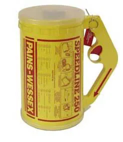
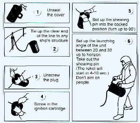
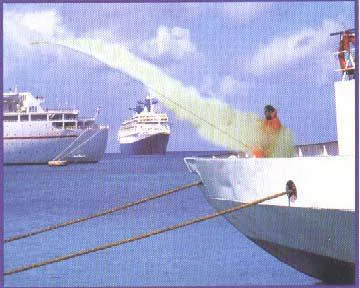
4 Projectiles × 230 m
- Carries 4 self-contained rocket projectiles
- Operational range ≥ 230 m in calm air
- Aerodynamically stabilized with integral propellant charge
4 Lines × 2 kN
- 4 buoyant, non-kinking flaked lines
- Breaking strength not less than 2.0 kN
- Flaked inside container to run free without snagging
Pistol / Integral Casing
- Stowed on the navigation bridge in water-resistant case
- Weather-protected safety trigger with removable safety pin
- Operating instructions stencilled legibly on exterior
2. EEBD (Emergency Escape Breathing Device)
EEBD = Emergency Escape Breathing Device. It is an escape-only set — for getting out of a smoke-filled or toxic space, never for going in to fight a fire.
Locations on a cargo ship:
- Accommodation: minimum 2, plus 1 spare.
- Engine room (ECR): 1; near the workshop: 1; at each deck or platform: 1.
- Stowed ready for use and easily visible — mostly in the engine control room, workshop and near escape routes — so any crew member can grab and don one immediately.
- Exact numbers and positions on your ship come from the Fire Control and Safety Plan.
- Brief instructions for operation and use, with diagrams or pictures, are provided with each set.
Construction — what is inside the set:
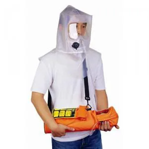
- Cylinder: a small cylinder carrying 2.5 litres of oxygen (breathing air), along with a demand valve and low-pressure alarm.
- Hood and facepiece: fresh air or oxygen comes inside the hood and the facepiece, which are connected to the cylinder through the demand valve.
- Clear window: a clear window is provided in the facepiece, made of flame-resistant material for clear sighting and smooth escaping.
- Pressure indicator: fitted so the wearer knows the remaining pressure, and knows the charging limit while charging the cylinder.
- Gives escape air for a service duration of not less than 10 minutes.
Wearing procedure (new type):
- Open the case and pull the hood out — removing the hood normally activates the air supply automatically.
- Pull the hood fully over the head, face looking through the clear flame-resistant window.
- Tighten the neck seal so smoke cannot leak in around the neck.
- Breathe normally — the demand valve feeds air on each inhalation — and escape immediately by the shortest safe route; never stop to fight the fire.
Prohibitions — what the EEBD is NOT for:
- Not for firefighting; not for entering oxygen-deficient voids or tanks; not to be worn by firefighters in place of a firefighter outfit.
Charging, checks and life:
- Charged with the ship's breathing-air compressor, using a suitable adaptor — otherwise it is charged by an external authority in port.
- Monthly checks: the indicator needle must sit in the green zone (proving no leak), and the case must be kept clean.
- Check and record expiry dates — a typical EEBD is valid for 15 years.
- Do not open the EEBD for practice; a separate training piece is carried and used for training purpose only so working sets stay sealed.
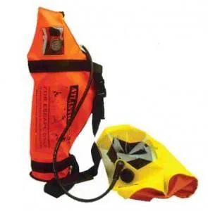
Required Shipboard Locations
- Accommodation: Minimum 2 sets + 1 spare
- Engine Control Room (ECR): 1 set
- Machinery Workshop: 1 set
- Machinery Platforms: 1 set at each deck level near escape routes
Prohibited Uses
- Firefighting: Strictly forbidden (air volume too low; no thermal body armor)
- Tank entry: Never use for work in oxygen-deficient or toxic voids
- Firefighter substitute: Cannot replace approved SCABA sets
Inspection & Service Life
- Monthly check: Verify manometer needle is in the green zone
- Service life: Maximum 15 years from date of manufacture
- Training: Never open working sets for practice; use dedicated training unit
3. SCABA Construction & Working Duration
SCABA = Self-Contained Air Breathing Apparatus — also called the BA set, SCBA or CABA (Compressed Air Breathing Apparatus) — used to supply fresh air when a person enters any space where the atmosphere is suspect and may not support human life. For "describe your BA set?" walk the air path from cylinder to mask.
When it is used:
- Entering an enclosed space whose atmosphere cannot be trusted.
- Entering a space to fight fire as part of the fire party.
Construction and air path:
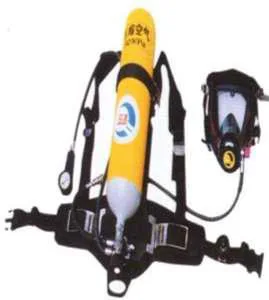
- Air cylinders: carried on a sturdy backplate with shoulder harness and waist belt; charged with compressed air up to 200 bar (single cylinder of 1200–1240 litres or two smaller cylinders).
- Reducing valve (pressure reducer): brings the high cylinder pressure of 200 bar down to a medium pressure of around 4 bar.
- Lung demand regulator (demand valve): brings the 4-bar medium pressure down to breathable atmospheric pressure; feeds air on inhalation.
- Full face mask: covers eyes, nose and mouth, made of hypoallergenic silicone or rubber with a panoramic visor giving a clear field of view, speech diaphragm and head harness.
- Exhalation valve: vents exhaled air out of the mask and prevents smoky or toxic ambient air from entering.
- Pressure gauge (manometer): mounted on the shoulder strap, continuously shows the remaining cylinder pressure.
- Warning whistle: sounds when the pressure drops to 55 bar ± 5 bar (50–60 bar), giving the wearer approximately 10 minutes of air to evacuate to safety.
Duration formula — the viva standard:
For a standard 1200 L set (6 L × 200 bar): 1200 ÷ 40 = 30 minutes total, minus 10 minutes safety margin = 20 minutes safe working time.
Air consumption rates by work rate:
- Resting: 8–12 L/min
- Light work: 12–20 L/min
- Moderate work: 20–40 L/min (standard planning average: 40 L/min)
- Heavy work: 40–60 L/min
Safety checks before donning:
- Cylinder pressure must not be less than 80% full when starting work.
- Check the gauge reading regularly; the whistle sounds at 55 bar ± 5 bar.
- When the whistle sounds, exit to a safe area by the shortest and safest route.
- Do not remove the equipment until in a safe area, clear of the hazard.
SCABA High-Pressure & Whistle Alarm Test Procedure:
4. Low-Pressure Alarm Test, Function Checks & During Use
Surveyors rigorously test candidate execution of the self-contained compressed air breathing apparatus (SCABA) safety sequence during oral and flag-state safety inspections. SCABA sets operate on a two-stage pressure reduction circuit designed to maintain positive internal facepiece pressure (+3.5 mbar), ensuring any peripheral seal compromise results in outward air leakage rather than inward ingress of toxic gases or superheated smoke.
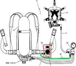
Low-Pressure Whistle & Leakage Integrity Test (Surveyor Execution Order)
Pre-Donning Facepiece Seal & Operational Checks
Statutory entry rule: cylinders must be at least 80% fully charged (≥ 240 bar for 300 bar sets) before entry. Air consumption must follow the Rule of Thirds: 1/3 air for entry and task execution, 1/3 for egress, and 1/3 safety margin. When the whistle triggers at 55 bar, approximately 8 to 10 minutes of escape air remain—wearers must immediately abort tasks and withdraw via the verified escape route.
5. Doffing, Mask Care & Maintenance Intervals
For "what do you do after using the BA set?" give the doffing order first, then mask care, then the interval ladder the surveyor ticks off.
After use — doffing order:
- Press the reset lever to switch to the OFF position; press and hold down the button and remove the demand valve.
- Removing the mask: insert the index fingers behind the tabs on the neck straps, press the buckles forward with the thumbs, pull the mask forward off the face and then up and back over the head.
- Close the cylinder valve and remove the facepiece.
- Unbuckle the waist belt, lift the shoulder-strap buckles to loosen, and remove the equipment.
Mask cleaning, disinfecting, drying and testing:
- Cleaning: the mask must be cleaned after every use — cloth with lukewarm water and all-purpose detergent, rinsed thoroughly under running water. Never use organic solvents such as acetone or alcohol.
- Disinfecting: place the mask in a disinfectant bath with approved disinfectants only — excessive concentration or over-long times damage the mask — then rinse thoroughly under running water.
- Drying: leave to dry in air at a maximum 60 °C, kept out of direct sunlight.
- Testing: the mask must be tested every time it has been used, repaired or serviced, per the maker instructions.
- Speech diaphragm: visually inspect — the diaphragm and O-ring must be clean and undamaged; clean or replace if not.
- Inhalation valve: visible in the mask connector — blow into it and check both wings of the valve disc move freely; replace if seized.
- Exhalation valve: remove the protective cap, press one arm of the spring clamp inward and remove it, lift the disc out by the nipple. Disc and seat must be clean and undamaged; moisten with water and refit — when the seat is horizontal the disc must slide into the guide under its own weight — then fit the spring clamp (marked L and R) at an angle.
Maintenance intervals — the statutory ladder:
Monthly Routine
- Inspect air bottles, bottle valves, and pressure reducers
- Check intermediate hoses, manometer, and harness backplate
- Test lung demand regulator and withdrawal warning whistle
Yearly Inspection
- Thorough test of all internal valves and sealing rings
- Check acoustic performance of speech diaphragm
- Functional test on calibrated test bench
Every 2 Years
- Mandatory replacement of exhalation valve disc
- Must be replaced regardless of whether mask was used
- Prevents hardening or micro-leakage in toxic atmospheres
Every 5 Years
- Major overhaul of reduction valve in authorized workshop
- Hydrostatic pressure stretch test of air cylinders ashore
- Immediate replacement of any bottle showing corrosion or impact
Clean with lukewarm water and mild detergent (no solvents) → Disinfect in approved bath → Air dry at max 60°C away from direct sun → Test speech diaphragm and confirm exhalation disc slides home under its own weight.
Surveyors commonly ask: "tell me about the line throwing apparatus / EEBD / SCABA including figures?" Answer one appliance at a time:
- Line throwing: 1 set, 4 × 230 m projectiles, 4 × 2 kN lines, yellow cylinder at 45 degrees with the wind, safety pin, bridge stowage, pistol weather container versus integral water-resistant casing.
- EEBD: accom 2 + 1 spare, ECR 1, workshop 1, each deck 1, 2.5 L demand-valve hood set, ≥ 10 min, never for firefighting, monthly green-zone check, 15-yr life.
- SCABA: open-circuit for enclosed space and firefighting, 1240 L ≈ 31 / 21 min, whistle 50–55 bar ≈ 10 min left, consumption 8–12 / 12–20 / 20–40 / 40–60 L/min, duration = capacity ÷ 40 − 10 (1200 ÷ 40 = 30 − 10 = 20), alarm test 200 bar → ≤ 10 bar/min → whistle at 55/60 bar, 80%-full rule, disc 2-yr, overhaul 5-yr.