
Four-Stroke Operation — Alternator Duty
What trips a generator engine, the start-to-load drill, and the gearbox watch that comes with it.
Key Principles at a Glance 5 points
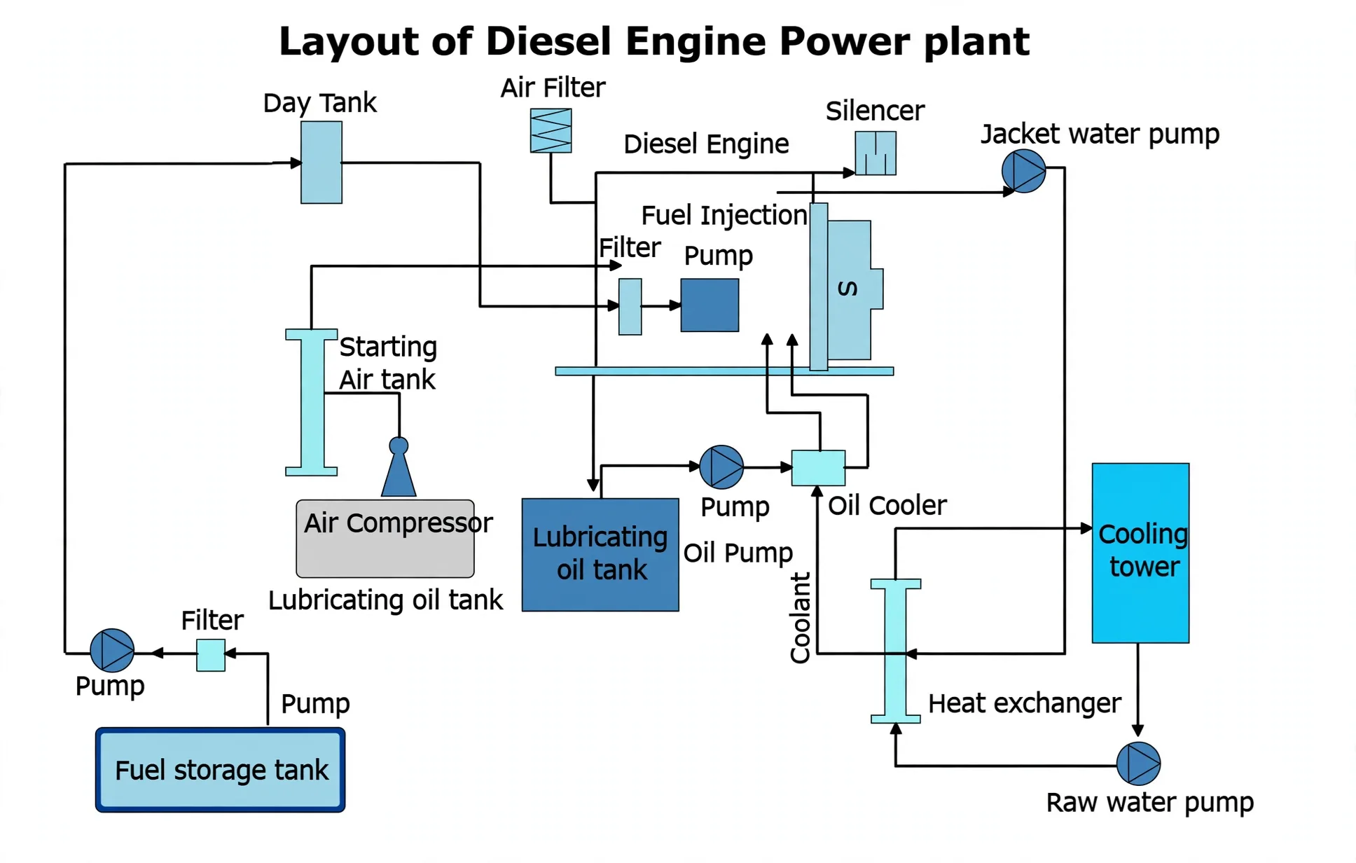
- Prime mover plus alternator is the shipboard power station: thermal to mechanical to electrical, with seven support systems around it.
- Three trips guard the engine (LO pressure, jacket temperature, overspeed) plus crankcase breathing, relief and mist detection with breaker-trip behaviour.
- Pre-op proves fluids, freedoms and positions: levels, heaters, racks, lubricators, separator state, barred cylinders dry, gear out and locked.
- Start at zero governor with free racks and 25–30 bar air; warm ten minutes, load gradually, cool 10–15 before stopping.
- Geared drive gets its own watch: sump level and condition, pressures with filter ΔP, temperature trends, vibration and noise.
1. Protection & Plant Map
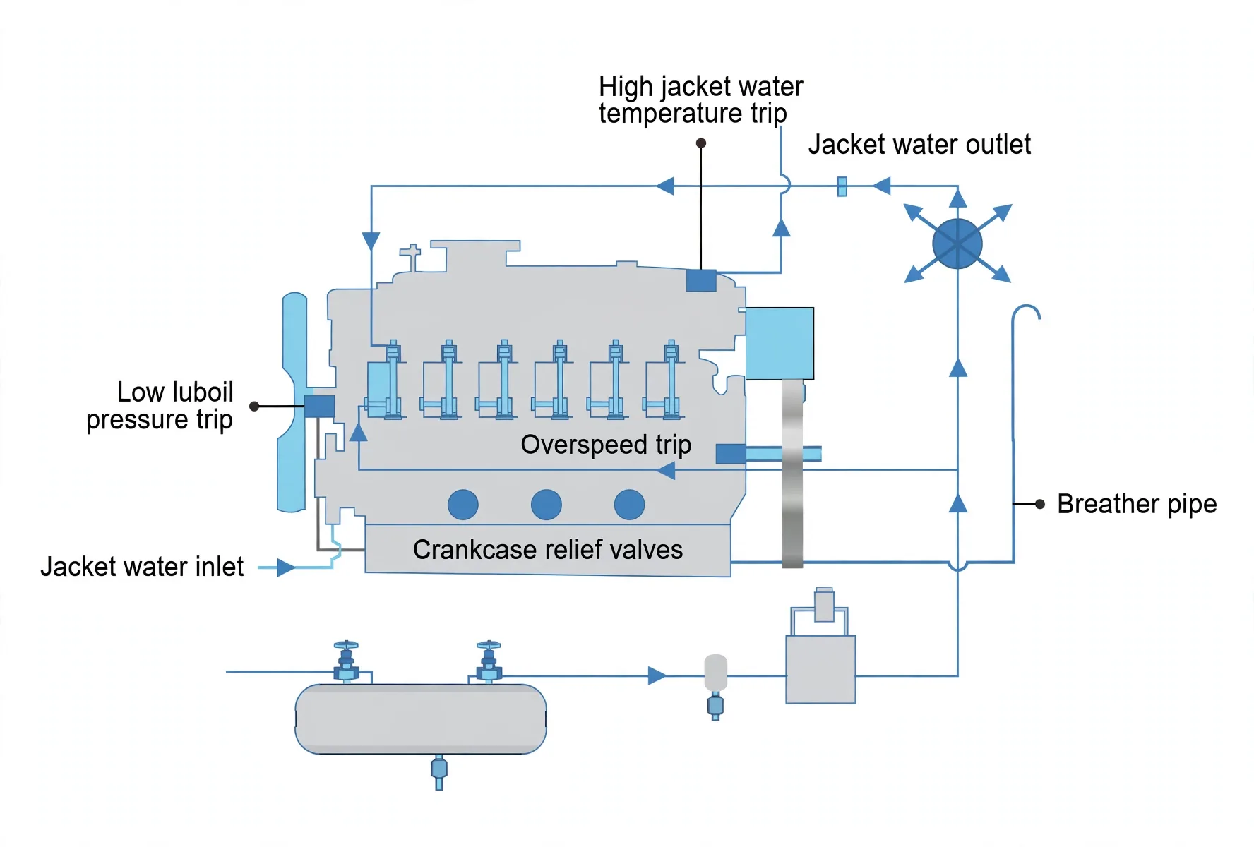
Low LO pressure and high jacket temperature trips each alarm then fuel-cut the engine; overspeed kills fuel to a standstill. The crankcase breathes through a flame-trapped breather, relieves through door valves against explosion, and watches itself through the mist detector — alarm always, auto slow-down on propulsion, breaker trip and off-load on generators.
2. Pre-Op & Start
Prove before starting:
Header and sump, turbocharger, governor and bearing levels correct.
Jacket-water and injector-cooling heaters on with valves correctly set.
Racks and plungers moving free; liners hand-lubricated without force.
Every system valve in position; separator run as needed (sump-to-sump purifying hours before, unlike main-engine practice).
Pre-lube running.
Cylinders barred dry through open cocks.
Heaters and circulating pumps off.
Gear out with lever locked.
Start sequence:
Alarms live; pre-lube, transfer, booster, nozzle-cooling, jacket and service pumps up.
Gear confirmed out and locked.
Indicator cocks open.
25–30 bar air proved.
Governor at zero with knob wound five turns.
Racks stroked free.
Main air valve open.
Clearance and GO from the duty staff — then start.
3. Run & Stop by the Clock
Cocks shut, ten minutes at speed warming, RPM eased up, load only on warm metal — then pressures to spec, per-unit jacket/LO/exhaust and turbo temperatures, turbo oil, filter differentials, service-tank water drains with positive head, header levels, sump trends (fast moves mean trouble), and ears open for knocks. Stop: load across first, breaker under ~50 kW, 10–15 minutes cooling running, speed down, stop button, cocks open, air valve shut, pre-lube off, slow barring over.
4. Gearbox & Coupling Watch
Single-reduction usually single-helical gearing with elastic couplings absorbing misalignment and torque ripple (clutch-combined where fitted, mechanical excluded from easy clutch duty). Watch sump level and oil state, pressures with filter differentials, temperature trends, vibration and noise — maker instructions overrule any generic list.