
The Sewage Treatment Plant — Aeration, Settling and Chlorination
The machine itself — its compartments, its flow path, its disinfection stage and its settings.
Key Principles at a Glance 8 points
- Three compartments do three jobs: the aeration chamber where the bacteria live and work, the settling chamber where the solids separate from the liquid, and the chlorinator where the liquid is made safe to discharge.
- Sewage is retained in the aeration tank for about 24 hours, aerated from the bottom, then displaced through a coarse screen into the settling compartment.
- The bubbles do two jobs: they supply the colony's oxygen, and they create the turbulence that prevents settlement and keeps the activated sludge in suspension.
- Settled solids are returned by air lift to the aeration tank — that return is the bacterial colony itself being recycled, and a blocked air lift sends it to an unaerated compartment where it goes anaerobic within a short time.
- The Trident variant adds a primary collection tank to buffer a bursty flow, and uses a porous fine bubble diffuser that needs clean air or it blocks and must be replaced.
- Disinfection is by calcium or sodium hypochlorite with 60 minutes' retention in the collection tank, or by ultra-violet radiation; the low level float switch that stops the discharge pump simultaneously opens the solenoid to the chlorinator.
- Desludging is about three-monthly and pumps out about three quarters of the aeration tank contents, never the whole tank, because the remaining quarter carries the bacterial colony forward.
- The equipment list specifies two rotary blowers and two discharge pumps, with the chamber operating between 0.5 and 0.8 bar.
1. The three compartments
The maker's manual governs the compartment volumes, the aeration rate, the chlorinator dosing and the desludging interval. Keep the plant running. An air supply failure is a biological failure, not merely a mechanical one.
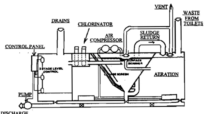
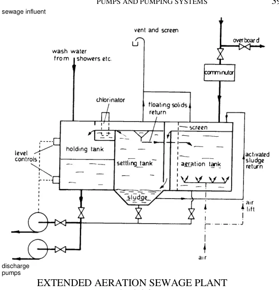
The unit is divided into three compartments: the aeration chamber, the settling chamber and the chlorinator.
That is the skeleton, and everything else hangs on it. The aeration chamber is where the bacteria live and work. The settling chamber is where the solids are separated from the liquid. The chlorinator is where the liquid is made safe to discharge.
2. The process, step by step
- Sewage enters the aeration tank through the soil inlet, and is retained there for about 24 hours, thoroughly mixed and aerated by the aerators located at the bottom of the tank.
- The aerobic bacteria and micro-organisms break down the organic wastes into mainly carbon dioxide, water and inert organic material, and in doing so produce new bacteria cells and organisms. The colony grows as it works.
- Air, providing the oxygen for the bacteria, is supplied by a rotary blower to the aerators. The aerators are easily removable through the side or end of the tank for replacement — a design detail that matters, because they block.
- The mixture is displaced by incoming sewage into the settling compartment, after passing through a coarse screen. The screen catches material that would otherwise foul the settling chamber.
- The settling compartment precipitates all solids to the bottom of the hopper as activated sludge. That sludge is returned by air lift back to the aeration tank, and mixed with the incoming raw sewage.
- The clean liquid is displaced into the chlorinator, to kill any remaining bacteria.
- The discharge of the harmless effluent is controlled by a float switch connected to the discharge pump.
- A combined surface skimmer and outlet weir at the centre of the settling tank removes floating debris from the surface and controls the flow of clean water into the chlorinator.
The bubbles do two jobs
Besides providing the oxygen, the bubbles create turbulence so that settlement is prevented and good mixing is obtained. This is worth stating explicitly, because it explains why aeration continues throughout the aeration chamber rather than being injected at one point. The air is not only the colony's oxygen supply; it is also the agitator that keeps the activated sludge in suspension.
Why the sludge return matters
Step 5 is the part that makes the plant work. The activated sludge returned to the aeration tank is not waste — it is the bacterial colony itself, being recycled so that it can digest the incoming raw sewage. A plant with a blocked sludge return line loses its bacteria to the settling chamber, where they go anaerobic within a short time.
3. The four-compartment variant
Not every plant has three compartments. The Trident system has four:
- Incoming waste passes through a coarse screen into the primary collection tank, where it remains until displaced by overflow into the aeration section. A connection is provided so that the primary collection tank can be pumped out.
- Air enters the aeration section through a fine bubble diffuser at the bottom. The diffuser is of porous material, so clean air is needed to prevent blockage.
- After prolonged aeration the mixed liquor is displaced into the settlement tank, where the biological floc is formed. Activated sludge gravitates to the bottom and is continuously withdrawn and returned to the aeration chamber by an air lift.
- Clean effluent from the top of the settling tank is collected in the last compartment for disinfection and discharge overboard.
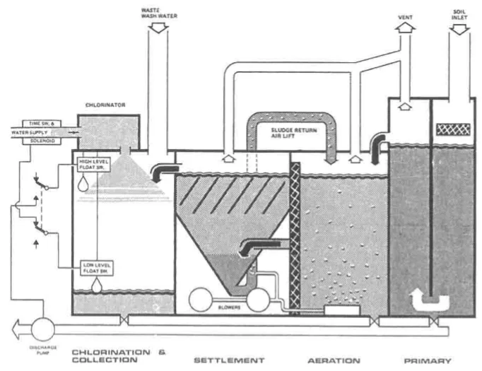
The difference is the primary collection tank, which buffers the flow. That matters on a ship whose sewage arrives in bursts rather than continuously.
The porous diffuser point is a maintenance issue, not a design detail. A fine bubble diffuser made of porous material will block if the air is dirty, and once blocked it must be removed and replaced.
4. Disinfection
The effluent leaving the settling chamber is clean but not sterile. Disinfection is the last stage.
How the discharge and the chlorinator are linked
Two float switches in the final section control the discharge pump. As the tank fills, the top float switch starts it. When the low level float switch stops the pump, it simultaneously opens a solenoid valve in the water supply line to the hypochlorinator.
In passing through the chlorinator the water forms a sterilising solution, and a timing device on the solenoid valve lets the correct amount into the treatment tank for the next charge.
The elegance of this is that the dosing is triggered by the discharge pump stopping, so the plant doses the incoming charge rather than the outgoing effluent. There is no separate dosing pump to control.
The Hamworthy method
The clear effluent is treated with calcium or sodium hypochlorite in a tank at the end of the unit. The chlorinator uses tablets of calcium hypochlorite in perforated plastic tubes, around which the effluent flows, dissolving tablet material as it does so. The treated effluent is held in the collection tank for 60 minutes to complete disinfection.
In some plants, disinfection is by ultra-violet radiation instead. No chemical is stored and no residual is carried overboard, but the lamp must be kept clean and the flow rate must be controlled.
The caution
Various sterilisation methods exist, and tablets of compound used in one method may become unstable and dangerous during storage. A tablet designed for one chlorinator is not interchangeable with another. Storage stability is a real hazard, not a theoretical one.
5. Keeping the colony alive
Every way of killing the colony, each with its mechanism, and the reason the settling chamber is the point at which the plant is most easily lost, is set out in Aerobic and Anaerobic Breakdown, section 3 and section 4. There is no need to repeat the biology here. The one thing worth carrying forward is that oil and grease is the commonest cause by a wide margin, and it is the one that gives no warning — a blower failure announces itself, a slow ingress of grease does not.
What does belong here are two facts about this particular machine.
The plant cannot be hurried back into service. With the extended aeration system it can be 5 to 14 days before the plant is fully operational again after a kill, because the prolonged aeration is what grows the colony. There is no faster route. That is why "keep the plant running" is an operating rule and not a preference — a ship whose plant has died mid-voyage has no treatment capacity until the colony returns, and no amount of mechanical repair shortens that.
A dead plant is not simply an idle one. Once the air stops, the contents are no longer being treated; they are digesting. The correct response is to shut the plant down, restore the air, and rebuild the colony, rather than to keep circulating sewage through a tank that has no oxygen in it. The gases that result from getting this wrong, and the entry precautions they demand, are in Safety on the Sewage Plant, section 2.
6. Desludging
Over a period of time the quantity of sludge in an aeration tank increases, due to the collection of inert residues from the digestion process. This build-up is measured in ppm or milligrams per litre, and the rate of increase is a function of tank size.
Most marine sewage treatment plants are designed to be desludged at intervals of about three months. The operation entails pumping out about three quarters of the aeration tank contents and refilling with clean water.
Note what is not done: the tank is not emptied. Three quarters is pumped out and the remainder is kept, because the remaining quarter carries the bacterial colony forward. Emptying the tank completely would be equivalent to shutting the plant down.
Regular removal of sludge prevents impairment of operation. Where the sludge goes once it is out of the tank — overboard at sea clear of restricted areas, to a sullage tank, or to the incinerator — is the subject of Sludge Disposal.
7. Equipment and settings
The important equipment on a sewage plant:
- Two rotary blowers — one running, one standby.
- Two discharge pumps.
- A safety valve at the aeration blower.
- A high water level activating switch.
- A low water level activating switch.
- A high water level alarm.
The chamber operates in the range of 0.5 bar to 0.8 bar. If the blower is damaged there is one stand-by blower for such emergency use — which is why the equipment list specifies two blowers and two discharge pumps. A sewage plant with a single blower has a single point of failure, and the consequence of that failure is five to fourteen days without treatment.
8. Alternatives to aerobic treatment
Physical and chemical treatment
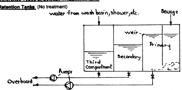
Physical and chemical treatment systems achieve breakdown with the aid of chemicals, and a circulation process, with sludge removed at intervals.
Chemical treatment plants are recirculation systems in which the sewage is macerated, chemically treated, and then allowed to settle. The clear, sterilised, filtered liquid is returned to the sanitary system for further use, and the solids are periodically discharged to a sullage tank or an incinerator.
The advantages are that there is no necessity to discharge effluent or sludge in port or in restricted waters, and that the plant is relatively small and compact.
The disadvantage is that chemical toilets are not always what they should be, and the relatively complex system brings increased maintenance.
The comparison with the aerobic plant is worth holding. The chemical plant solves the zero-discharge problem elegantly — nothing leaves the ship — but it does so at the cost of complexity and of a dependence on chemicals that has its own failure modes.