
Steering Gear — Ram vs Vane, 12-Hour Test, Filters, Oil Charging & Air Purging
How a bridge helm order becomes rudder torque — and the test, filter, charge and purge routine that keeps it air-free.
Key Principles at a Glance 6 points
- Bridge order becomes rudder torque through control, servo pump and power unit — two independent power units, each able to steer alone with auto-changeover.
- Within 12 hours of sailing the full chain is proved on each unit in turn: hard-over to hard-over, alarms, indicators, auto-start and auto-restart.
- Hydraulic oil must be particle-free: 50-micron pump-inlet filters plus return-line silt filters, serviced on pressure drop or red visual indicator.
- Storage tank stays 90% full for one complete emergency recharge; running sumps hold 75% with ullage left for expansion and return flow.
- Air compresses while oil does not — purge every cylinder until bubble-free oil runs, then prove with helm orders from bridge and flat.
- Emergency drills every 3 months rehearse the trick-wheel local control, bridge communication and alternate power supplies.
1. Two Circuits, One Rudder — Where the Oil Goes
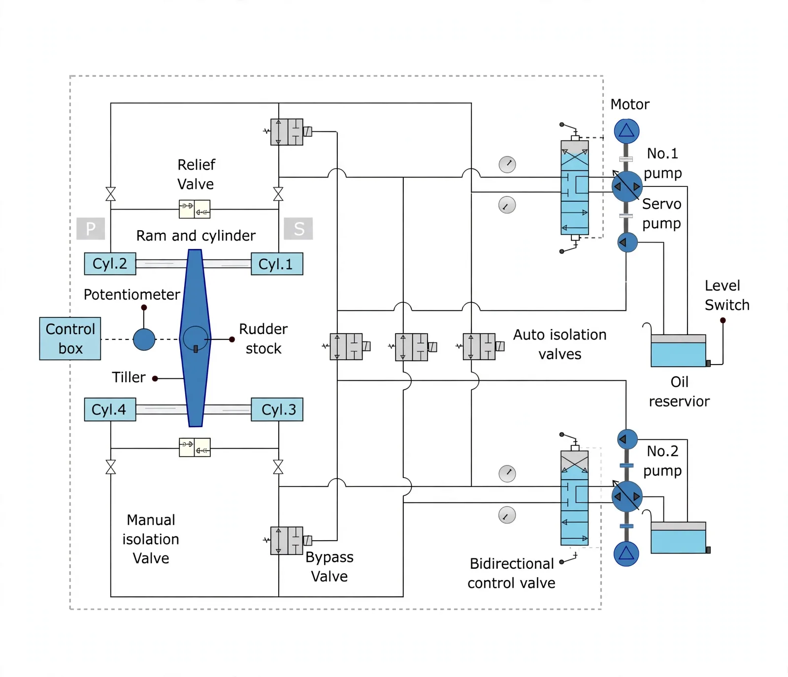
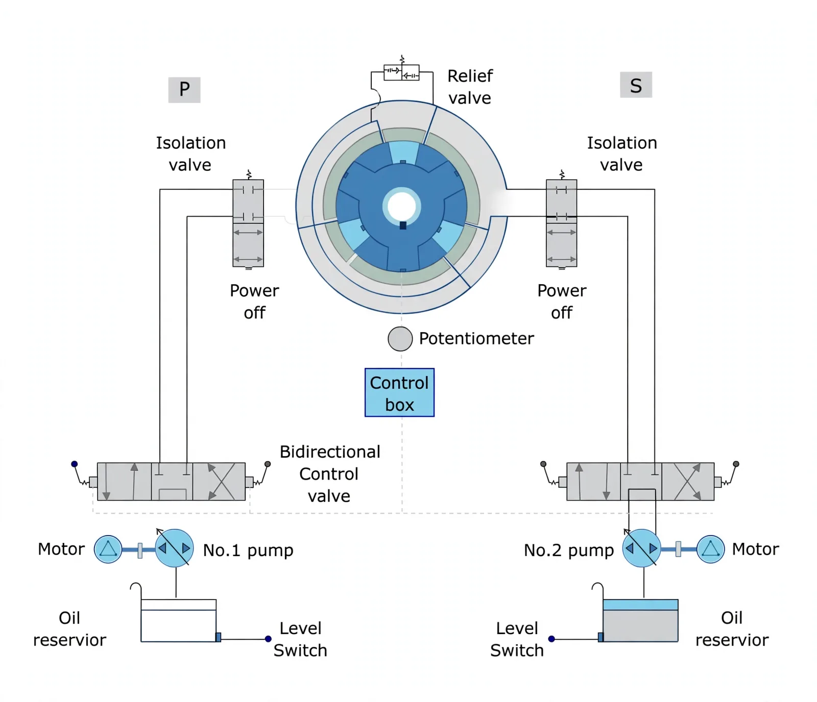
One line explains every steering gear: a helm order meters pilot pressure, pilot pressure strokes the pump, pump pressure moves the stock. Two complete power units stand ready, and each alone must steer the ship — if the running unit fails, automatic changeover brings its twin in.
Ram type — push-pull on a tiller
Two pairs of opposed rams (Cyl. 1–4) push the tiller both ways. Relief, bypass, manual and auto-isolation valves ring the circuit, so a burst line is cut out while the healthy pair keeps steering.
Rotary vane — pressure straight onto the stock
Pressure acts on vanes fixed to the stock inside a sealed casing — no tiller, no rams. Isolation valves on each side let one half run while the other half is cut out for repair.
2. The 12-Hour Test — Prove the Whole Chain Before Sailing
One line first: the test fails a unit on purpose to prove its twin takes over — steering is verified by surviving a staged failure, not by running smoothly. Within 12 hours before departure the crew checks all nine statutory items: main and auxiliary gears, remote control systems, every bridge steering position, emergency power, rudder-angle indicators against the actual stock, control power-failure alarms, power-unit failure alarms, and auto-isolation gear.
Quarterly drills rehearse direct control inside the flat with the trick wheel, bridge communication, and alternate power supplies. Short-voyage ships may test weekly instead, by administration waiver — and where extra non-mandatory equipment is fitted, the same drill rules apply to it.
3. Daily-to-Drydock Rhythm & Safe Isolation
One line first: most steering failures announce themselves as heat, noise, weeps or low level days earlier — the routine exists to catch the whisper before the shout. Rams run lubricated with system oil, and ram guides take grease through individual nipples or a central system, verified full while running.
| When | What | Why it matters |
|---|---|---|
| Daily | Sliding parts and linkages lubricated; pump seals and pipe joints watched; reservoir level, oil temperature and pressure, pump amperes vs normal; replenishing + storage tank levels | Drift here is the earliest warning of wear, aeration or overload |
| Weekly | Alarms and emergency changeovers; bridge-to-flat communication, repeated on sound-powered telephone | Changeover that fails in harbour would fail in a narrow channel |
| Monthly | Hydraulic filters cleaned or renewed per maker | Dirt scores pumps and sticks servo valves |
| 3-monthly | Emergency steering from the local station, logged | Proves the flat crew can steer without the bridge loop |
| 6-monthly | Oil samples sent ashore for lab analysis | Water, particles and oxidation show before symptoms do |
| Drydock | Continuous-survey overhaul: ram seals renewed, bearing wear-down measured | Restores the clearances the sea years consumed |
4. Filter Service Without Trapping Air
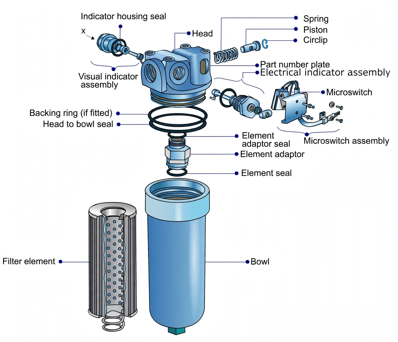
One line first: filters sit at the two places dirt hurts most — pump mouth and oil homecoming — and every service ends with the air let back out. The pump inlet carries a 50-micron element that stops chips and debris; the return line carries silt (return-line) filters that polish oil coming home.
Isolate the circuit and prove zero line pressure at the purge screw — opening a live filter sprays oil and ingests air.
Turn the base down slowly, lift bowl with element — fit a new element, or solvent-wash plus ultrasonic-clean a wire-mesh one, then air-blow it dry.
Reassemble, then purge through the plug until air-free liquid runs — because any bubble left here travels straight to the servo.
Start the pump, give helm orders, and walk every joint for weeps — the service is only done when steering answers crisply and stays dry.
5. Charging Oil — One Full Recharge Always in Reserve
One line first: the storage tank is not a top-up can but a lifeboat — it must always hold enough for one complete circuit refill. Charging runs from the storage tank through a hand pump into the selected oil reservoir: valve positions matched to the gear nameplate, gear on local control first.
Change to local control and match every valve to the gear nameplate — charging on remote risks a helm order mid-fill.
Open storage-tank outlet, hand-pump valves and the target reservoir filling valve; hand-pump until the reservoir rises as the storage tank falls.
Stop with ullage to spare — expansion and return flow need the space — then shut reservoir filling valve, storage outlet and hand-pump valves.
A brim-full reservoir has nowhere for hot expanded oil or returning flow to go — vents lift, seals weep, and the next purge reads false.
6. Purging Air — Bubble-Free at Every Screw
One line first: oil is incompressible so helm orders arrive instantly; air compresses, so every bubble left inside turns a helm order into a delayed sponge. Purge the 4-ram gear cylinder by cylinder: hand-drive first with the system isolated, then motor-drive under local control through each pump in turn.
Isolate, confirm the sump at 75%, insert the turning bar, and crack every cylinder air-release screw — because air hides in the highest dead-end of each ram.
Hand-drive: stroke the pump, walk the gear slowly both directions until bubble-free liquid escapes at every screw, then stop stroking and stop turning.
Motor-drive: breaker on, local control, move the gear side to side with gradually increasing ram travel — first on one pump, then the other via the changeover switch — checking releases periodically.
Tighten screws only when every point runs clear, then cross-check with helm movements ordered from both bridge and flat — crisp answer both ways is the pass mark.