
Reefer Oil Control, Separators, TEV & Safety Cutouts
Why oil must leave the compressor but come straight back — and the valve that holds superheat at 3–6 °C.
Key Principles at a Glance 7 points
- Oil lubricates, cools and seals the compressor — but as an insulating film in the evaporator it kills cooling, so it must be caught and returned within moments.
- Separators stack four tricks — velocity drop, direction change, coalescence, centrifugation — and a float needle returns only clean oil on system differential pressure.
- A cold oil-return line means liquid refrigerant flashing inside: the shell is too cool or the sump floats on mixture, not oil.
- The TEV balances phial pressure against evaporator pressure plus spring to hold 3–6 °C superheat — starved opens it, flooded closes it.
- Evaporator pressure drop above 0.15 bar (Clyde field rule) demands an external equalising line, or the valve chronically starves a healthy coil.
- Clyde rooms run meat −18 °C, fish −2 °C, veg +6 °C — each thermostat drives its own ON/OFF solenoid, and the TEV itself is a throttle/pressure-reducing valve.
- Protection is three manual-reset cutouts: oil-differential below 1.2 bar (time-delayed for start-up), HP on over-pressure, LP on suction loss.
1. Oil: Essential in the Crankcase, Poison in the Evaporator
One line first: the same oil film that seals the compression gap becomes a thermal blanket the moment it reaches the evaporator — so the plant is designed to lose oil and recover it continuously. In the cylinder, oil lubricates the sliding wall, carries frictional heat away as vapour, and seals the compression clearance — but piston motion whips it into a liquid–vapour–aerosol flux that leaves with the discharge gas.
Note on grades: mineral, synthetic and semi-synthetic stocks exist (paraffinic vs naphthenic families); the choice must not react with the refrigerant in use. Clyde's separator footnote: a separator is fitted where oils are immiscible with the refrigerant (will not mix) — separated oil returns to the crankcase and clean gas goes on to the condenser. What the examiner wants is the loop logic: separate fast, return immediately, keep almost nothing away from the crankcase at any moment.
2. Four Separation Tricks in One Vessel
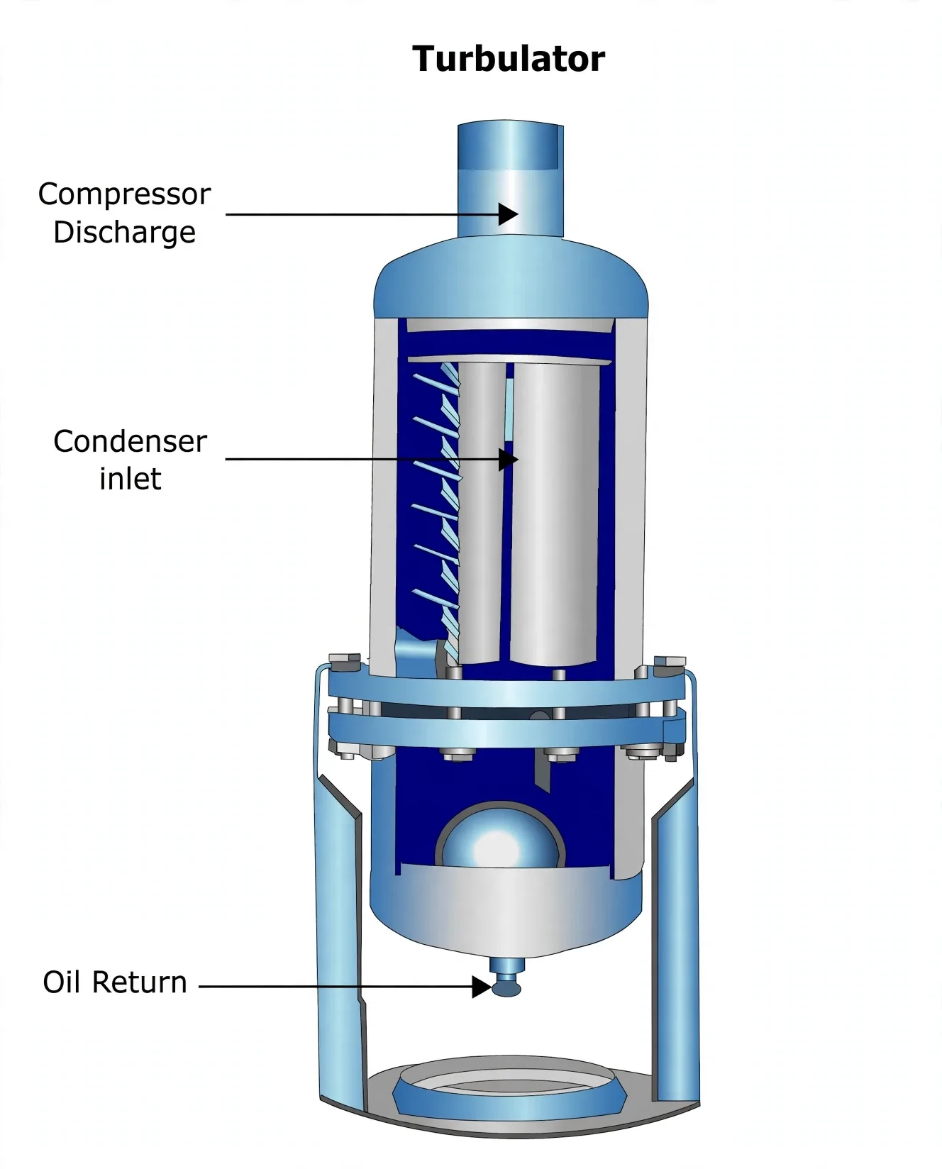
One line first: oil droplets are heavy and vapour is light — every technique inside the vessel is just a different way of giving weight time to win. Makers combine up to four, and the discharge fog meets them in order: slow down, turn, merge, spin.
Velocity drop
Discharge gas enters a huge internal volume and slows abruptly — heavy droplets can no longer stay airborne and fall out.
Direction change + baffles
Fog is forced around baffles; droplets keep their line by inertia, strike surfaces and run down to the sump.
Coalescence
Metallic sieves and coalescing cores merge fine mist into heavy drops that drain by gravity — cores are renewed on schedule.
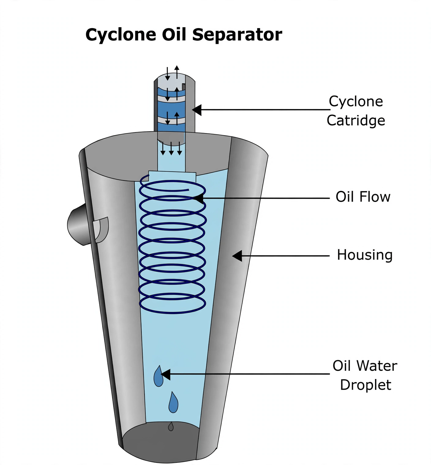
Centrifugation
Spun flow flings dense oil outward while light vapour exits centre — the cyclone cartridge principle.
3. The Float Return — Small, Automatic, Diagnostic
One line first: system differential pressure pushes high-side oil home to the low-side crankcase, and the float admits it one sip at a time. A float riding the sump opens a needle valve only while clean oil stands high enough, then shuts it as the level falls — so little oil is ever absent, and only clean oil returns.
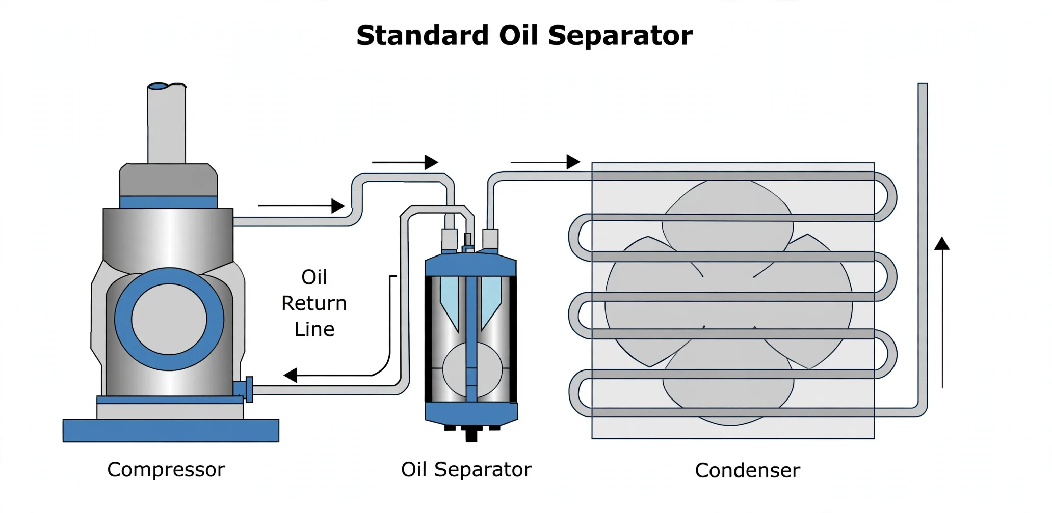
A healthy return line runs just above ambient from conducted separator heat. Cold to the touch means liquid refrigerant is flashing inside it — the shell runs too cool (poor insulation over-cools discharge gas, condensing liquid into the sump) or the sump floats on mixture, so the float lifts too often. Fix the cause, not the symptom.
4. Oil Charging & Strainer Routines
One line first: oil is only added to a pumped-down compressor, through a non-return valve, from sealed containers — because opening a live crankcase wastes charge and invites air. Replenish when the sight glass reads below half; makers specify the grade (typical reefer spec: ISO VG 68, VI 143, flash 230 °C, pour −42 °C — fluid in polar rooms, stable at discharge heat, rust-inhibited).
Pump down: close the receiver-outlet liquid valve and let the compressor pack the charge into the condenser until LP trip — because the crankcase must be worked on empty.
Shut suction and discharge. For charging: connect the hand pump to the non-return crankcase valve and fill to level. For the strainer: vent trapped gas to a retrieval bottle, drain over a tray, pull the strainer off the drain plug and clean it.
Secure the valve, refit caps, reopen suction, delivery and receiver outlet, restart — and renew the charge if foaming, carry-over or seal leakage has degraded it.
5. The TEV — Superheat Held at 3–6 °C
One line first: the TEV is a tug-of-war that never ends — phial pressure pulls open, evaporator pressure plus spring pull shut, and the rope settles where superheat is 3–6 °C. Its three duties: drop condenser pressure to evaporator pressure across the orifice (flash gas forms, cooling begins), feed exactly the evaporator's load, and hold steady outlet superheat so no liquid reaches the compressor.
On large or multi-circuit evaporators the coil's own pressure drop fools the valve into chronic starving. Clyde's field rule: once the drop across the evaporator coil exceeds 0.15 bar, pipe the bellows underside straight to suction piping between phial and compressor (external equaliser) so the valve sees true outlet pressure instead of inlet pressure. For the sister lesson on weighing charge, hunting leaks and reading the fault table, see Reefer Servicing — Charging, Leak Repair, Defrost & Faults.
TEV in one exam sentence: a throttle and pressure-reducing valve — high-pressure liquid in, low-pressure cold mixture out — whose opening is continuously re-trimmed by the superheat balance above.
6. Running Gear — Cutouts, Rooms & Back Pressure
One line first: the plant runs itself on room thermostats and stops itself on three cutouts — everything else is monitoring. Two equal-capacity plants sail together so one covers the other's maintenance; each room holds its thermostat setpoint through its own ON/OFF solenoid — Clyde's rooms: meat −18 °C, fish −2 °C, veg +6 °C (so a meat-room thermostat set at −18 °C lets high-pressure liquid through its evaporator only until −18 °C is reached, then the solenoid shuts it). A timer defrosts cold-room coils automatically; parameters are logged for trend-watching.
| Guard | Senses | Trips / resets |
|---|---|---|
| Oil-differential | Lube-oil pressure vs suction pressure | Below 1.2 bar differential → trip, manual reset; time delay allows pressure to build at start-up |
| HP cutout | Compressor delivery pressure | Above set value → trip, manual reset |
| LP cutout | Suction pressure | Below set value → trip; doubles as the normal start/stop control holding room temperatures |