
Shell & Tube Heat Exchangers — Cleaning, Retubing & Leak Detection
Heat crosses from hot fluid to cold through the tube wall — fouling, scale and galvanic attack all fight that crossing, and every routine exists to keep the wall clean, sealed and protected.
Key Principles at a Glance 6 points
- Maintenance runs on calendar time and performance, not running hours — oil and water keep circulating and fouling even with the machinery stopped.
- A shrinking temperature differential across tube nest or shell is the first sign of fouling; the daily log catches it before performance collapses.
- Leakage runs from the higher-pressure oil or jacket-water side into the seawater side; find the tube by trickle, halo or bubble test, name it by the shell-pressurisation drill (+1 bar, leaker weeps), plug both ends, and retest.
- Floating-tube bundles grow with heat: shrink-fit tubes ride between a bolted fixed plate and a sliding floating plate while shell corrugations flex — fix both ends and the bundle buckles.
- Zinc or soft-iron anodes only protect what they are wired to — the jump wire or collar-stub continuity path matters as much as the anode itself.
- New joints and O-rings are obtained before opening, register marks go on before unbolting, and jack bolts — never levers — free the stack.
1. Know Your Cooler & Its Routines
Heat crosses the tube wall from the hotter fluid to the colder one — usually oil or jacket water on the shell side giving up heat to seawater inside the tubes. Anything coating that wall (scale, deposits, oil film) is insulation that strangles the crossing, and the inlet-to-outlet temperature difference on each side is the report card that shows it.
Calendar time, not running hours: main-engine lube oil keeps circulating even with the engine stopped, so fouling never sleeps. Study the maker's manual before touching anything, and follow this rhythm:
| When | What |
|---|---|
| Daily | Log temperature differential across the tube nest and across the shell — a shrinking differential is the first sign of fouling. |
| 15 days | Open inspection covers, look at the tube side, assess fouling, plan cleaning. |
| 3 months | Backflush; circulation-clean the tubes with maker-recommended chemicals. |
| 6 months | Inspect sacrificial anodes and their securing (renew if wasted); inspect sealing rings (renew if damaged or brittle); mechanically clean tubes; circulation-clean the shell side and outer tube surfaces. |
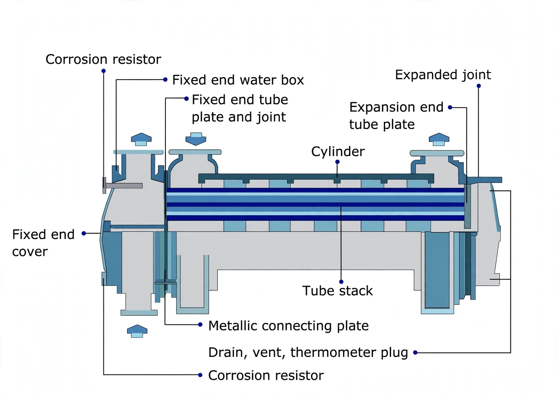
Floating-tube construction — one end fixed, one end free (Clyde)
The hot bundle grows longer than its shell — fix both ends and something buckles. So the tubes are shrink-fit with one end in a fixed plate and the other in a floating plate that slides as the bundle expands, while corrugations in the shell flex to take up the same growth. The expansion end in Figure 1 above is this idea in service: the joint that moves instead of stressing.
2. Isolate Safely — the Checklist
Pressure and hot fluid do the injuring, not the tubes — so isolation proves, step by step, that no fluid can still reach you before a spanner turns. Each step verifies the previous one.
- 1Shut the cooling or heating medium — seawater or steam valves closed.
- 2Shut the process fluid — lube oil or freshwater valves closed.
- 3Prove isolation — open the vent cock or purge valve; any flow means a valve is passing and isolation has failed.
- 4Confirm full drain — both fluids completely out. If it is an oil cooler, drain the oil while still warm so it flows freely.
- 5Secure and warn — all pipeline valves secured and a men-at-work notice displayed before any routine begins.
3. Clean It Three Ways — Backflush, Mechanical, Chemical
Each cleaning method attacks a different bond: backflushing reverses shear to lift loose inlet deposits, brushing scrapes adhered scale the flow cannot move, and chemicals dissolve films and pits that bristles cannot reach. Always start with the least effort and assess before escalating.
Backflushing (no dismantling)
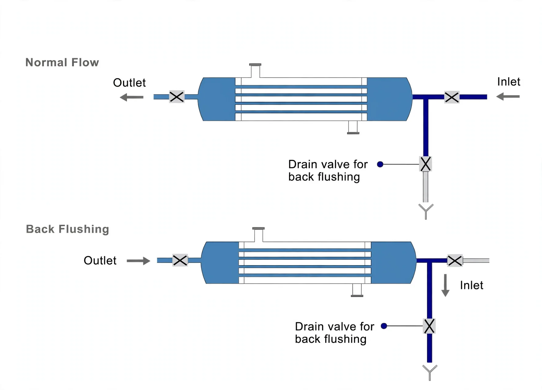
Reverse one or both fluid flows for a short period. Reversed flow applies reversed shear to the deposit layer at the inlet, lifting it off so it washes out the way it entered. Least effort — always try this first, then assess the improvement.
Mechanical tube cleaning (end covers off)
- 1Isolate and mark. File register marks on the end covers, slacken the nuts, open the covers.
- 2Inspect as you open — end covers, division plate and anodes; record what you see because it tells you where the cooler suffers.
- 3Brush every tube with the maker's long-handle tools to clear scale and obstructions — manual brushing is the only remedy once deposits have hardened.
- 4Rinse thoroughly with freshwater so loosened debris cannot resettle.
- 5Renew wasted anodes and the cover-to-shell joint, reopen system valves and check for leaks.
Chemical circulation cleaning (fouled beyond brushing)
Brushes cannot reach into pits or touch shell-side oil films — chemicals can. Match the agent to the film: maker-recommended degreaser for oil on outer tube surfaces, descaling liquid mixed in proportion with freshwater for a freshwater medium being cooled, and maker-recommended chemicals for tube-side circulation cleaning.
- 1Mark and remove the shell-side connecting pipes (register marks first).
- 2Mix the maker-recommended chemical in the correct proportion with freshwater.
- 3Circulate — connect shell side (or tubes) to a circulating pump drawing from the chemical tank, returning to the reservoir.
- 4Hold temperature and time exactly per the maker's recommendations — chemistry only works at its rated condition.
- 5Strip, rinse and dry — freshwater rinse after the stipulated time; alternatively dismantle and immerse the whole tube stack in a tank of cleaning solution.
4. Defeat Galvanic Corrosion
Dissimilar metals plus seawater form a battery that never switches off — seawater is the electrolyte, the joined metals are the electrodes, and the less noble metal dissolves. Deposit layers make it worse by breaking the passive oxide film locally through velocity and temperature differences, and chloride ions then drive pitting; aluminium alloys suffer where anodic matrix meets cathodic copper or nickel alloying elements.
Sacrificial anodes
Pure zinc or soft iron in the water boxes, fitted with a bolt or stud through the same material as the box. Lower in the galvanic series than any cooler part, they corrode instead of tubes and baffles — renew when wasted.
Guaranteed continuity
The anode only protects what it is wired to. Maintain the jump wire or jump plate between tube plate and water-box flange (or collar studs) and refit the metallic connector strip on assembly — continuity is paramount.
Coatings + watch spots
Epoxy paint inside water boxes. Corrosion hotspots are water boxes and tube plates — inspect them first, every time.
5. Dismantle → Retube → Assemble → Test
A failed tube is a failed pressure boundary — retubing restores it by cutting the old tube out, seating a new one, and roller-expanding its walls plastically into the plate holes so metal grips metal with no welding. Tube failure traces to adverse operation or careless maintenance; use only the correct maker tools.
Get a new set of joints and O-rings before opening the unit, and read the maker's retubing instructions.
Dismantle
- 1Isolate and drain both fluids (oil warm); file register marks across shell, tube plate and water-box flanges so alignment is guaranteed on reassembly.
- 2Remove the metallic connector strip, unbolt and lift the fixed-end water box, then the joint ring.
- 3Lift the expansion-end box with its machined leakage ring and two joint rings, then the tube stack.
Never lever under the fixed-end tube plate — it damages the plate and guarantees leaks on reassembly. Break the stack free with jack bolts tightened evenly and diagonally first. Hoist horizontal stacks on a leather sling, vertical ones on the centre eye-bolt (a tapped hole is provided at the centre of each tube plate). Handle with great care — tolerances are close.
Retube — standard tools
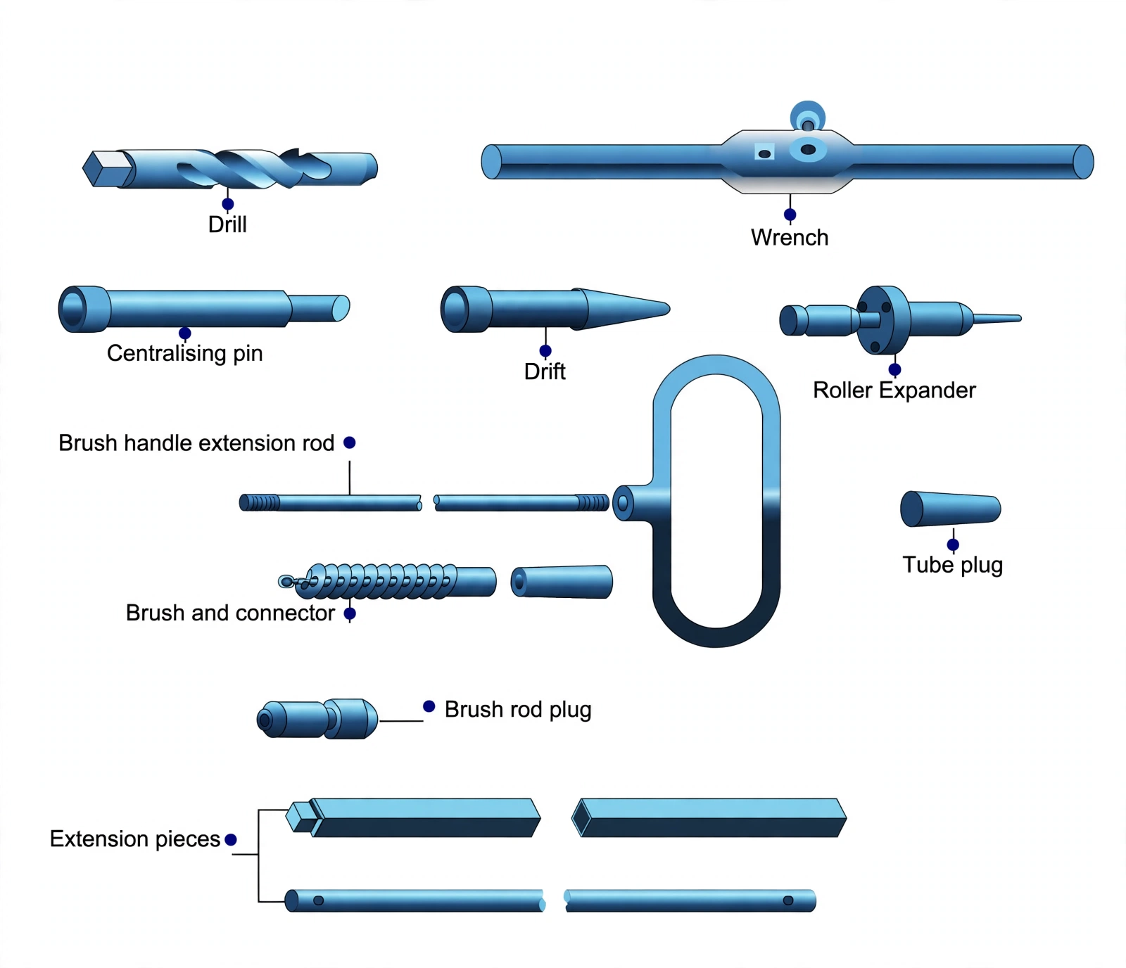
- 1Free the expansion end: fit the drill in the wrench, fill the flutes with grease, drill out the expanded tube section until free; clear burrs.
- 2Free the fixed end: insert the centralising pin, drill the fixed-end tube end, clear burrs, drive the pin as far as possible into the expansion-end plate.
- 3Work the tube out from the fixed-plate end with the wrench locked over the drill.
- 4Fit the new tube: clean plate holes, insert the tube, secure each end with a taper drift, then roller-expand clockwise with hand pressure — no forcing — at both ends. Expanding deforms the tube wall plastically outward into the plate hole, forming a metal-to-metal seal.
Retube — extension tools (tight or deep tubes)
- 1Drill out each end of the defective tube with the special drill extension.
- 2Thread the brush rod — screw rod sections together, pass through the tube, fit the brush-rod plug on one projecting end and the handle on the other.
- 3Pull steadily on the handle, rotating the tube to ease it through tight places; use the wrench once the tube clears the box.
- 4Taper-drift and roller-expand the new tube at both ends as above.
Assemble & pressure-test
- 1Rebuild in order: clean all internal surfaces; pass the flat joint ring over the stack and insert it without damage; align every register mark on shell flange and fixed-end tube plate; mount the fixed-end water box on a flat joint ring with clean metal-to-metal contact surfaces; fix the contactor strip; then stack the expansion-end inner joint ring, safety leakage ring and outer joint ring over the expansion-end tube plate and mount its water box — tightening all nuts progressively and evenly to avoid local overstressing.
- 2Close up: replace water-box covers, inspection doors and drain plugs.
- 3Pressure-test: blank the shell-side entries, fill the shell with freshwater, apply the correct test pressure, and examine tubes, plates and joints. A weeping new tube-to-plate joint gets a light re-expansion — then retest.
Find and plug a leaker
Jacket water and lube oil run at higher pressure than seawater, so leakage flows into the seawater side — heavy leakage shows as unexplained loss of jacket water or oil. Tubes with complete failure are replaced; leaking tubes are plugged.
| Method | When | How |
|---|---|---|
| Trickle test | General first choice (slow — be patient) | Covers off the seawater side, tube stack secured with dog clamps so it cannot shift under pressure, seawater side cleaned; circulate freshwater or lube oil outside the tubes — the leaker shows as liquid trickling from a tube end or tube-plate junction. |
| Fluorescent halo | Tiny leaks, no time to dry the spaces | Dissolve fluorescent sodium crystals in the water surrounding the tubes; view plates under UV — even a trace leak glows as a sharp halo despite damp plates. |
| Soap bubble | Time available and cooler isolable | Isolate the whole cooler, pressurise the shell side with air, brush soap solution on tube ends — bubbles mark the leaker. |
Which tube exactly — the shell-pressurisation drill (Clyde)
The table above proves a leak; this drill names the tube. Open the shell drain first — liquid there only says a tube leaks, not which. Then: remove the end cover; drain tubes and shell; blank the shell outlet; fill the shell from the inlet with working medium; clamp the removal end to the shell face; pressurise the shell with a hand pump against a calibrated gauge, 1 bar above working pressure — and watch: the holed tube weeps liquid from its open end. That is your leaker; plug both ends and retest.
AP Singh's running-engine read (p157): with a generator lube-oil cooler leaking in service, higher oil pressure pushes oil into seawater — check oil traces near the overboard discharge and watch the sump fall toward a low-level alarm. After stopping, the gradient reverses: seawater now out-pressures oil, sump level rises on contamination, then oil weeps from the aft seal near the flywheel (hole-size sets how fast). Confirmation is the same drill: close the seawater valve, remove the end cover, start the lube-oil pump — oil comes out of the leaky tube.
Lower pressure drop across the tube sheet, buildable in any size, simple enough for the ship's crew to overhaul, doubles as a receiver in refrigeration, preferred for lube-oil cooling under pressure differentials, and anodes can protect the whole cooling circuit. Its prices are paid in lower heat-transfer efficiency, withdrawal space for the tube nest, and fixed capacity once built.