
Piston, Liner & Rings — Wear, Clearances & Overhaul
The top third wears most, each ring needs three clearances, and the lift sequence protects the fragile gland first.
Key Principles at a Glance 6 points
- Wear concentrates in the top third — peak pressure, peak temperature, slowest piston — and calibration must project it forward to the next overhaul.
- A liner is condemned at 0.6–0.8% diameter growth; ovality and clover-leafing are honed round before gauging, never gauged as-is.
- Each ring seals by gas pressure behind it, spreads oil along the wall, and ferries crown heat into the liner — three jobs, three clearances.
- Clearance errors write their own failure notes: hammering and pumping from wrong axial, blow-by from wrong butt, dead sealing from packed back clearance.
- Withdrawal protects the fragile links first: carbon ridge off, spacer tube guarding the gland, tapped holes cleaned before the lifting tool goes on.
- Standing orders prevent repeat failures: cards before levers, tested injectors, correct viscosity, 50 °C scavenge air, dosed jacket water, re-pinned cam timing.
1. Liner Calibration — Measure Where It Wears
Idea first: the liner wears fastest where life is hardest — top third, where combustion pressure peaks, temperature peaks, and the piston crawls slowest through dead centres. So calibration measures there, at identical points every survey, and projects the rate forward.
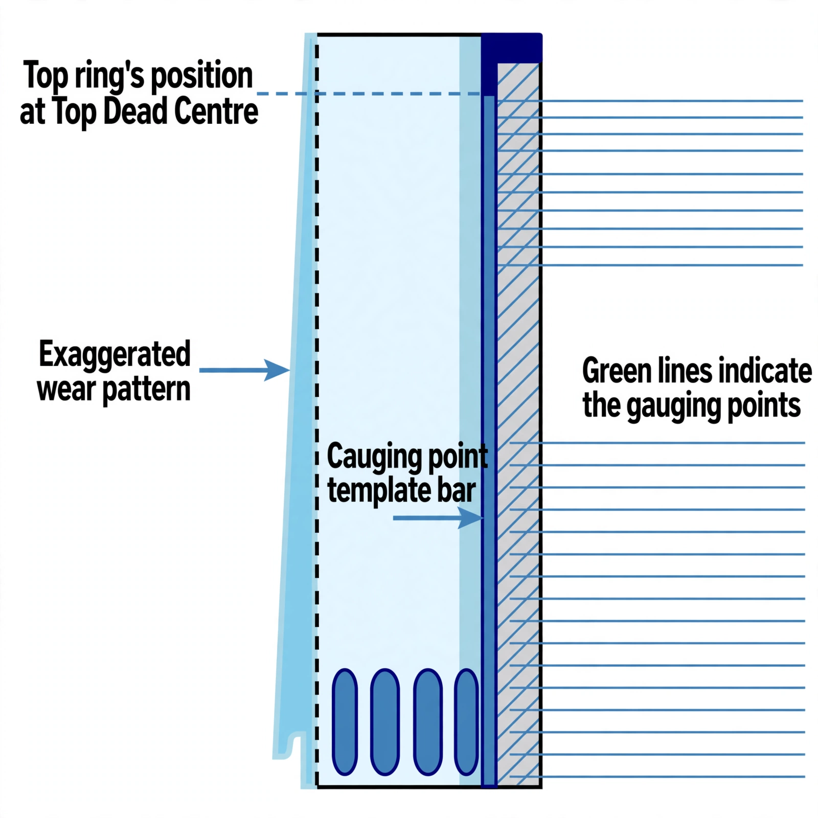
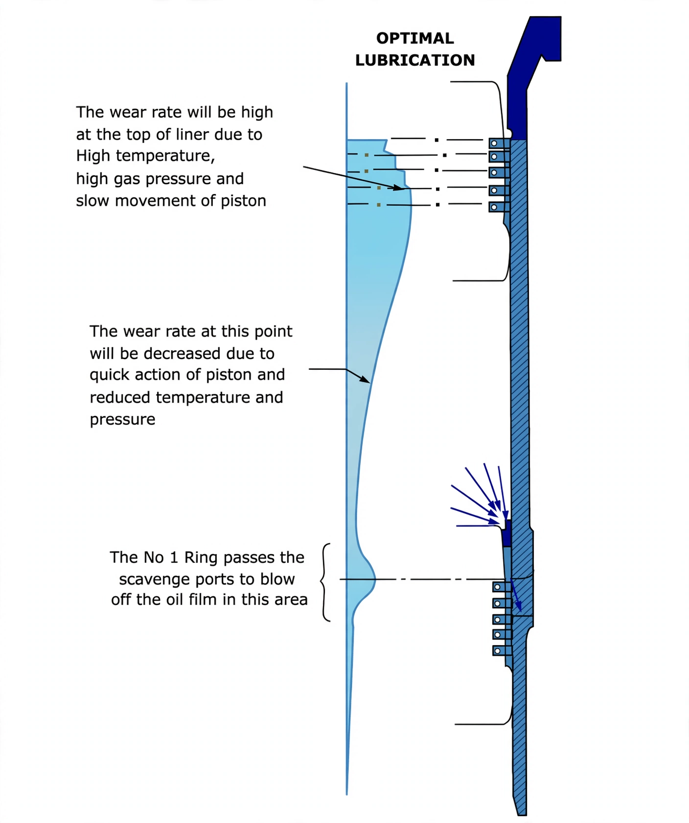
Four wear modes to name: friction (materials, lubrication, load), corrosion (sulphur acids), abrasion (hard debris), adhesion and scuffing (local welding of ring to wall). Side-thrust from rod angularity ovals the bore until rings cannot seal.
If the liner shows ovality or clover-leafing, hone it back to circular first — then calibrate. Gauging a distorted bore bakes the distortion into every future rate. Investigate any micro-seizure and restore lubrication before accepting the numbers.
2. Crown — Heat In, Cracks Out
Idea first: the crown cannot expand freely — geometry, constraints and temperature gradients lock it — so heat becomes stress. Thin the metal by corrosion and erosion and the gradient steepens until cracks open.
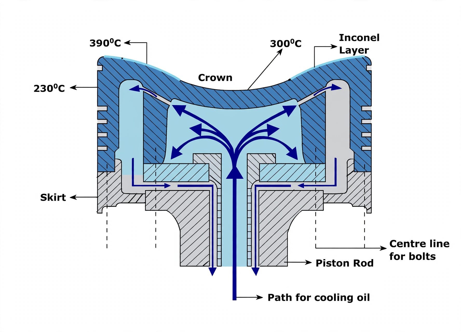
Carbon-choked cooling spaces overheat the same way. Two standing defences: keep stuffing boxes tight against cylinder-oil contamination of the cooling oil, and run LO pumps at least 30 minutes after stopping so the piston actually cools. Late-burning fuel eats the top surface; the cure is timing, injector health, correct viscosity and quality adjustment for high-CCAI fuels.
3. Rings — Three Jobs, Three Clearances
Idea first: the ring's own spring is only the starting push — combustion gas admitted behind the ring does the real sealing, pressing harder exactly where it is hottest and the film is thinnest. The same ring meters oil along the wall and conducts crown heat into the liner.
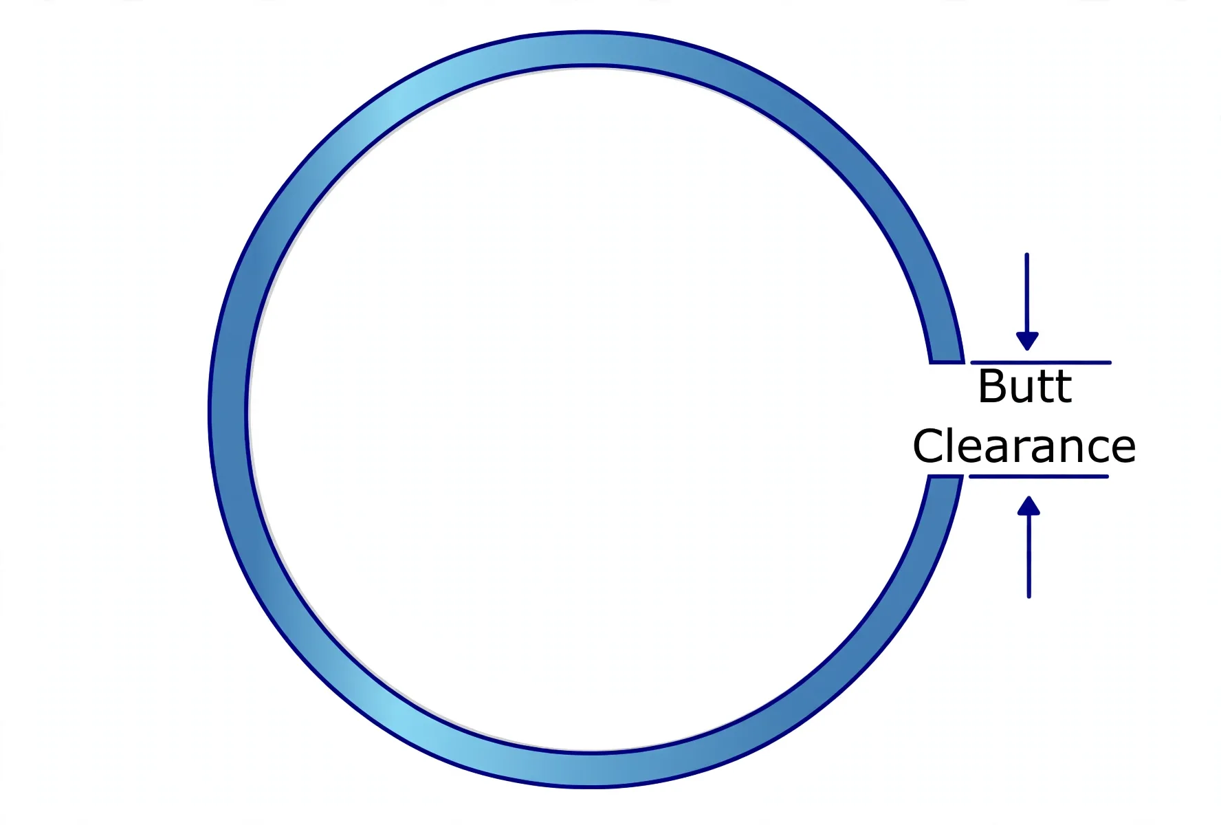
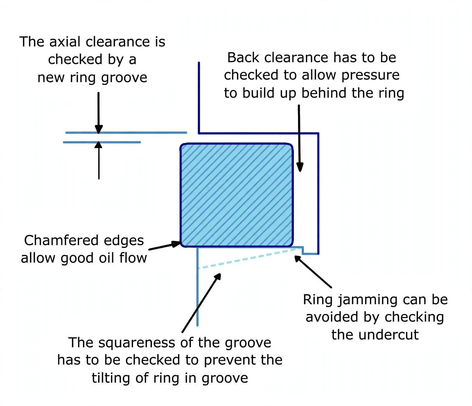
| Clearance | How checked | Purpose | Wrong size writes |
|---|---|---|---|
| Axial | Feeler at ring top, new ring in groove, several places round | Expand without jamming; slide out onto the wall; admit gas behind | Excess hammers and twists to breakage, pumps oil on four-strokes; shortage jams on carbon |
| Butt / circumferential | Ring in unworn liner section, gap measured | Growth room around the bore, worn-to-unworn travel included | Excess blows by locally and overheats; shortage seizes the ring in the bore |
| Back | Wood-push test in situ; tension felt by hand | Gas passage behind the ring plus slide-back freedom | Carbon-packed back clearance leaves the ring unseated and dead; poor springiness flags a broken ring |
Fitting discipline: part numbers to the manual (rings differ by position), butt clearance tried in an unworn bore section first, grooves gauged with a new ring, rings fitted bottom-first the right way up with the proper expanding tool, groove squareness and undercut confirmed so the ring cannot tilt and scrape the film. Rectangular sections carry small edge radii for the oil wedge; running-in stays at reduced load because a tilting new ring runs on edge pressure — overload then means blow-by burning the film off into micro-seizure.
4. Withdrawal — Protect the Fragile Links First
Idea first: everything lifted is heavy except the parts that damage easiest — the gland, the threads, the rings on the way past the liner mouth. So the sequence clears the path, guards the gland, and only then takes the weight.
Before a spanner turns: LO, FO, CW and start air isolated and locked off, turning gear engaged, jackets drained as needed, engine cooled, immobilisation approved, risk assessment done, permits in hand, spares confirmed, crew briefed with certified lifting gear and jacks proven leak-free — and the bridge confirms the shaft area is clear for turning. Nobody works the scavenge space on another unit mid-lift.
Drain the cylinder's cooling water fully — so a disturbed liner cannot flood the space.
Open the top: clear the path for the lift:
- Head and pipework off — so nothing fouls the withdrawal.
- Crank to BDC — so the piston sits low for ridge access.
- Grind the carbon and wear ridge out of the liner — so the rings exit without catching.
Unbolt rod from crosshead; bolt the two-piece spacer tube to the rod foot — it guards the gland on the way out.
Free the gland housing; crank to TDC so the spacer drives the gland out of its seat — gland leaves with the rod.
Tap-clean crown holes (water-softened carbon, special tap), torque the lifting bracket evenly, and crane piston, rod and gland into the cradle — upright on a special stand, or chocked and lashed if laid down.
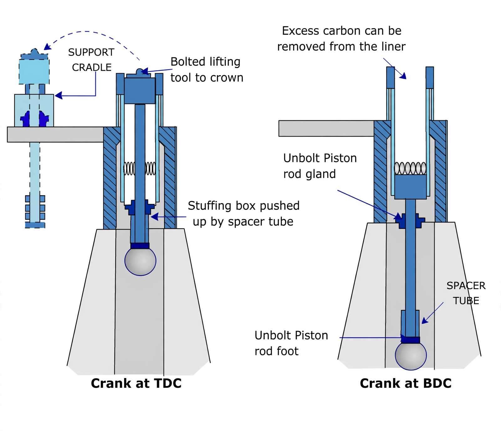
Bolts screwed fully home and torqued evenly, every threaded hole and bolt checked for damage first — a pulling-out tool drops tons. Work in squads with breaks capped around four hours, full PPE, and only competent certificated hands on the lifting plant.
5. In the Cradle — Strip, Measure, Prove
Idea first: the cradle turns the piston from a moving part into a measuring bench — every surface is read against a true datum (new rings, profile gauges, crack detection) before any decision to reuse is made.
Expand rings off with the proper tool — so rings and grooves survive removal undistorted; record old-ring wear to set the renewal decision.
Gauge grooves with a new ring, chrome plating and undercut checked, groove square — so wear reads against a true datum and rings cannot tilt and scrape.
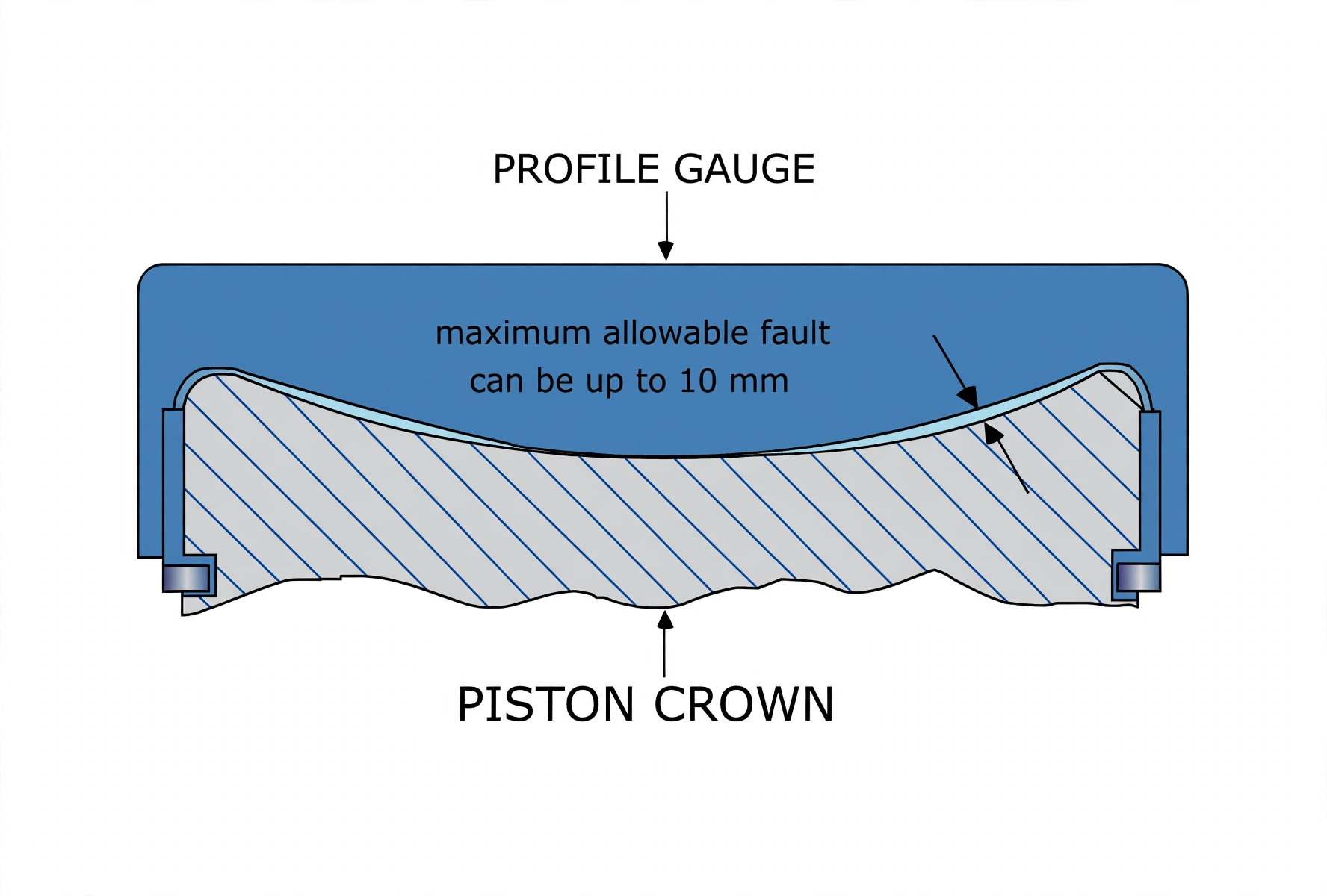
Profile-gauge crown burn-away and crack-test on suspicion — so thinning past limits or hidden cracks condemn the crown before refit.
Read ring faces and skirt for scuffing and abrasion — the marks give the fuel and air filtration plus lubrication verdicts; skirt wear flags crosshead misalignment or excess guide clearance.
Split rod from piston and inspect cooling spaces: shot-blast carbon, descale water sides, check fretting and O-ring lands — so crown heat escapes instead of cracking the metal. Strip and inspect the stuffing box rings and springs with it.
Gauge every bolt for stretch and inspect rod for wear and scoring — so yielded bolts are renewed instead of failing in service.
Hydraulic-test the reassembled cooling space without over-pressurising, with new O-rings and locking devices — so leaks show up without straining the joints.
New rings go in order, correct side up, axial and circumferential clearances proven in unworn bore sections first.
6. Reading Failures — Broken Rings, Seizure, Scuffing
Idea first: failures are the clearances and the film testifying after the fact — a broken ring says it was flexed to fatigue, a scored liner says metal touched metal, a scuffed skirt says the whole unit went thirsty or crooked.
| Finding | Mechanism | Correction |
|---|---|---|
| Broken rings | Worn liner lets rings pump in and out until gas pressure tilts and fatigues them; hammering grooves, jamming then radial shock in unworn bore, port-bar catches on worn edges | Withdraw, gauge grooves and liner, renew crown, rings and liner as measured, restore port-bar radii. Blow-by, lost compression and liner scoring follow if run on — a jammed fragment seizes the unit. |
| Micro-seizure (vertical scoring) | Starved film → metal contact → weld-tear: thin lubrication, blow-by burning the film off, scavenge water washing it away | Mild: restore oil, ease load, dry the scavenge air and let surfaces run back in. Severe: hone or renew liner with new rings and proper running-in. |
| Skirt scuffing | Skirt and liner film failure; with ring seizure alongside, whole-unit oil starvation or crosshead misalignment | Lubrication system first, alignment second — check fuel viscosity, injector health, cooler and jacket temperatures, rack balance and indicator cards before dismantling. |
Before blaming combustion, rule out the simple killers: fuel viscosity against the viscotherm and maker band, fuel specification limits, scavenge air temperature and cooler differentials, jacket and piston-cooling inlet and outlet temperatures, rack balance between units, power and draw cards for overload or bad injection and timing, injector sizes and lift pressures, pump wear, VIT and camshaft timing.
Standing orders that prevent all three:
- Study power and draw cards before touching racks, VIT or quality levers — and only on senior instruction.
- Bench-test every injector with correct nozzles — so spray quality cannot wash the film off.
- Hold injection viscosity to the book — so atomisation stays in the designed band.
- Keep scavenge air at 50 °C by PMS-cleaned coolers — so charge density and cooling stay as designed.
- Dose jacket water to spec — so liner temperatures stay out of the corrosive and scuffing bands.
- Re-pin camshaft timing after any chain work — so injection and exhaust events land where the designer put them.