
Crankshaft Deflection, Vibration & Failure Prevention
The shaft bends because bearings wear unevenly — a dial gauge reads the bend, balance weights steady the shake, and barred speeds dodge resonance.
Key Principles at a Glance 7 points
- The full shaft weight hangs on the main bearings — uneven wear bends the shaft, and breathing webs are how the bend is read.
- Valid readings need even keel with recorded drafts, propeller clear, turning-gear pinion unloaded and the gauge on maker-marked spots every time.
- Five readings per crank (top, port, starboard, two flanking bottom averaged) — port-minus-starboard reads horizontal, top-minus-bottom reads vertical.
- The cumulative deflection curve points at the faulty bearing: smooth is healthy, a kink is guilty.
- Slip to about 5 degrees is recoverable by hydraulic cam re-timing; gross slip is jack-back or new shaft — and a jumped web means the shrink fit is destroyed.
- Fatigue, torsional vibration, wiped bearings and hydraulic lock each have a named prevention — alignment checks, barred-speed discipline, oil care, torqued foundation bolts.
- Secondary forces shake twice per turn and moments rock end to end — weights and compensators oppose them, firing order spreads the rest; critical speeds are barred, transited fast, never held.
1. Why the Shaft Bends
Idea first: the crankshaft has nowhere to sit except on its main bearings. When they wear — never perfectly evenly — the shaft sags between high supports and hogs over low ones, so each crank web breathes open and closed as it rotates. Deflection measurement is simply reading that breathing.
A degree of misalignment is acceptable within limits. Past the maker's rating it becomes fatigue loading — and fatigue breaks shafts. That is why deflections are trended survey to survey, not just judged once.
2. Measurement — Five Readings, Zero Interference
Idea first: the readings are tiny and every outside force — trim, propeller weight, a lifting turning-gear pinion — bends the shaft more than the wear you are hunting. So the procedure is mostly about removing interference, then reading five points per crank.
Set conditions: propeller clear before turning, vessel upright at even keel with forward and aft drafts recorded, engine immobilised per SMS, enclosed-space procedure observed — and every survey at the same trim, or readings stop being comparable.
Prove the gauge: press the spring contact through full travel and back — it must return silkily, because any sluggishness falsifies everything. Convention: clockwise (webs closing) reads negative, anticlockwise (opening) reads positive.
Fit on marked spots between the webs exactly where the maker marked — position never changes between surveys, since a moved gauge is an added variable, not a true reflection of conditions.
Unload the turning gear: at the unit beside the turning gear, turn the pinion back so it cannot lift the flywheel — a lifted flywheel writes a false reading into the neighbouring crank.
Read five positions per crank: top, starboard, the two flanking bottom readings (10–15° after BDC on one side, just before BDC on the other, averaged), then port. Start the unit nearest the gauge position and check the flywheel angle so every unit begins from the same crank angle. No markings? Find TDC geometrically (AP Singh p46): lay a bridge with its graduated rod in the indicator hole (or drop a rod/chain through the fuel-valve hole onto the piston) and bar the engine until the rod reads highest — that is TDC; mark equal drops port and starboard of the peak (equal readings mean equal angles), take the midpoint as true TDC, verify by repeating from the other side, then set the flywheel pointer to it.
Reduce: port-minus-starboard gives horizontal alignment, top-minus-averaged-bottom gives vertical. Check against maker allowable limits.
3. The Curve Finds the Bearing
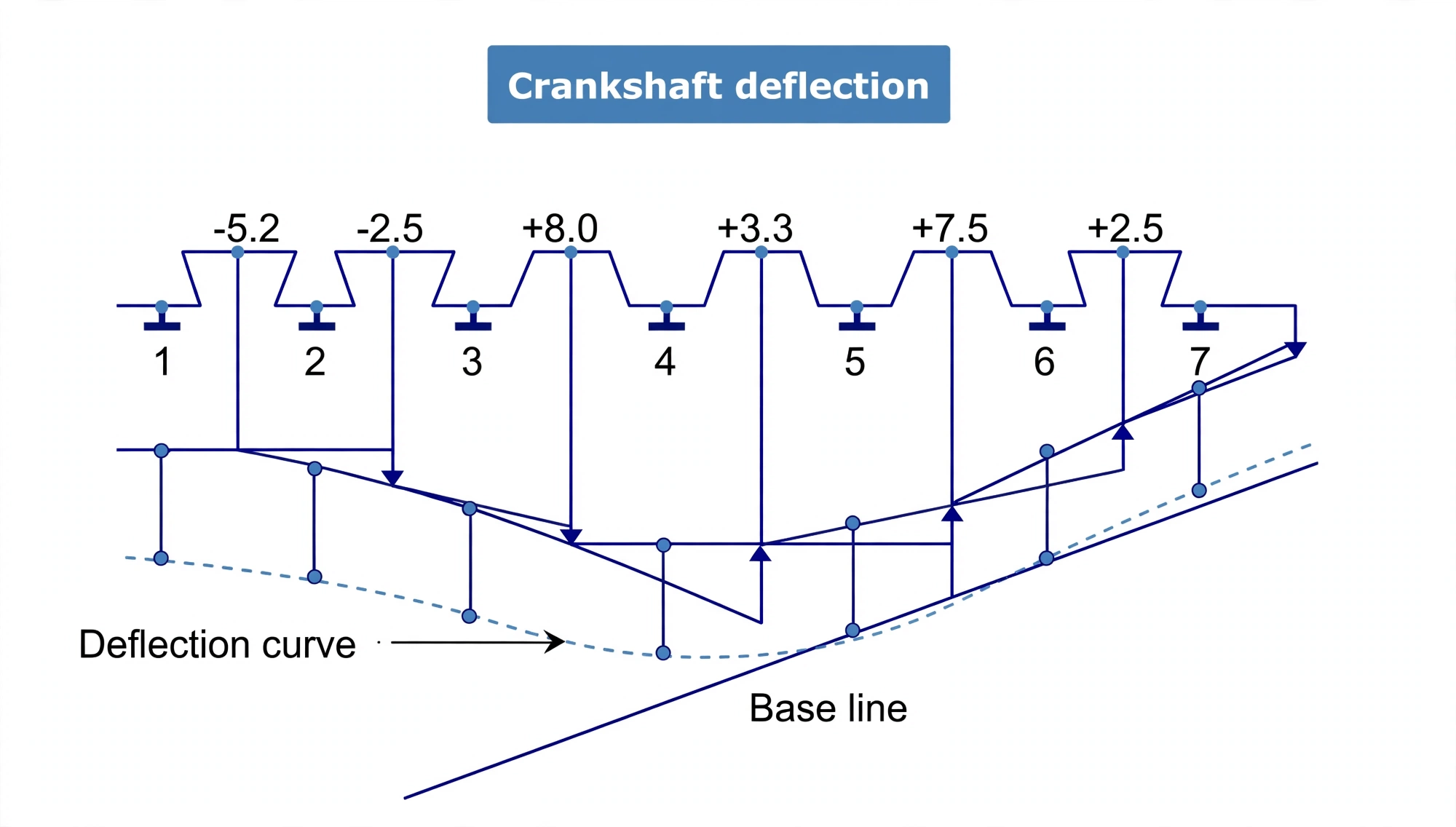
Idea first: one crank's reading only says that crank is bent — but progressively adding each vertical reading from one end of the engine draws the shaft's actual shape, and the kink in that shape sits over the guilty bearing.
How to draw it: starting from one end, progressively add each crank's vertical misalignment to the running total and plot the points. Uniform deflections draw a smooth curve; the curve is allowed to deviate at each crank by an angle proportional to that crank's deflection — an unequal deviation, a kink, isolates the faulty bearing for opening.
4. Journal Slip — the Punch Marks Tell
Idea first: the journal is only a shrink fit inside the web eye — overload it hard enough and the steel spins inside the steel. The punch marks straddling web and journal, once one straight line, step apart and confess exactly what happened.
Evidence of slip: stepped punch marks, shifted injection, exhaust-valve and air-start timing on affected units, turbocharger surge from the altered gas flow, and new vibration.
Small slip (to ~5°)
Alter fuel-pump and exhaust timing on affected units by hydraulically expanding and rotating the cams. Air-start timing stays slightly out, but multi-cylinder overlap absorbs it. Avoid resonant speeds and monitor — the slip must not walk.
Gross slip
Two choices: change the crankshaft, or attempt the jack-back recovery below. It is the heroic option, not the default.
Jack-back recovery — how the shrink fit is re-made. Chill the pin to shrink it while heat expands the web eye, then drive the web home with the journal locked:
Chill the pin with liquid nitrogen or dry ice — so it contracts inside the web eye. Allow several hours.
Mount the jack on battens — so jacking load spreads instead of denting the bedplate locally.
Warm the web with a broad flame, usual precautions — so the eye expands around the chilled pin.
Lock the journal against rotation — remove bearing shims and tighten the keep down — so nothing else moves while jacking.
Jack the web home gradually to its witness mark — so it creeps back instead of jumping past.
If the throw refuses to creep and then jumps suddenly past the witness mark as pressure rises, the shrink fit is torn — the metal has yielded and the shaft must be replaced. Never jack a slipped web back cold.
5. Why Shafts Break & How to Stop It
Idea first: every broken shaft is fatigue, overload or starvation finishing something an inspection could have caught — cracks propagate fast once started, so the precautions are all about catching the start.
| Failure root | Mechanism | Prevention |
|---|---|---|
| Cracks in webs, pins, journals | Propagate very quickly once started, ending in rupture | Alignment checks catch developing defects; respect condemning limits |
| Excess deflection → fatigue | Overload cycling, often originating at oil-hole lips and section changes | Investigate any substantial inter-bearing wear difference at its cause |
| Torsional vibration | Twist oscillation along the shaft from firing pulses; at a critical speed it resonates and cracks pins and journals — axial vibration stretches the shaft endwise with the same barred discipline | Never operate in the barred critical-speed range; transit it quickly without lingering |
| Wiped bearings | Starved lubrication destroys the white metal | Treat and tend lube oil properly |
| Hydraulic lock | Water in the cylinder stops the piston dead; failed relief valve lets force reach the shaft | Keep relief valves verified lifting; keep water out of cylinders |
| Unbalanced secondary inertia | Reciprocating masses shake the engine twice per revolution vertically; unbalanced moments rock it end to end | Balance weights and compensators oppose the shaking forces; firing order spreads residual unbalance along the shaft |