
Motor Starters — Taming 8–10× Current
Why a starting motor gulps current, the maths that tames it to one-third, and the contactors that must never meet.
Key Principles at a Glance 5 points
- A standstill rotor is maximum slip through minimum resistance — 6–10× full-load current until speed builds, and the bus tolerates only a 15% dip.
- Star puts line volts ÷ √3 on each phase, so line current and (voltage-squared) torque both fall to one-third — delta reconnects for full running.
- K1 mains plus K3 star start the motor; the timer drops K3, proves it open, then closes K2 delta — K1–K3 interlocking exists because star-plus-delta is a bolted short.
- A delta-built motor held in star at full load forces √3× rated phase current through its windings — it burns unless the overload relay saves it.
- Auto-transformers trade bulk and cost for tunable taps on any winding; soft starters ramp RMS volts by late thyristor firing — speed still needs hertz, never volts.
1. Why Starting Gulps Current
Idea in one line: at standstill the rotor is a shorted low-resistance cage cut hardest by the field, so current follows impedance alone — and impedance is at its lowest.
Three facts collide at zero revs: rotor bars (not wires) with shorted end rings give a fat low-resistance path, slip sits at maximum so the rotating field cuts hardest, and with no mechanical output yet the current is limited by winding impedance only. Result: a direct-on-line start throws 6–10× full-load amps at the bus, collapsing as the rotor catches up.
Small drives ride this out on DOL — full volts through one contactor, simplest and cheapest, no current limiting. Slow-moving heavy-duty loads cannot: the heating effect of prolonged starting current plus the voltage dip that malfunctions neighbours demand reduced-voltage starting every time.
2. Star-Delta Maths — One-Third Current, One-Third Torque
Idea in one line: starve each phase of volts by √3 and current falls by √3 per phase while line current — and voltage-squared torque — falls to one-third.
| Star (start) | Delta (run) | |
|---|---|---|
| Phase voltage | VL ÷ √3 ≈ 58% of line | VL — full line volts |
| Line current | ⅓ of DOL | Full DOL running |
| Starting torque | ⅓ of DOL (torque ∝ V²) | Full rated torque |
| Needs | Six-terminal delta-duty motor | Changeover at speed, never before |
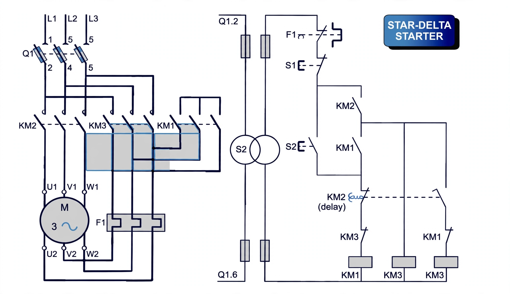
Why the changeover can never wait: a delta-designed motor held in star at full load forces √3× rated phase current through windings built for less — overheating to burnout unless the overload relay saves it. Star is a starting posture, never a running one.
3. K1/K2/K3 — The Changeover That Must Never Meet
Idea in one line: star and delta short the supply through each other, so the control circuit proves one dead before the other may live.
K1 (mains/line) + K3 (star) close together — motor accelerates in star on one-third current while the timer runs.
At speed the timer drops K3 and proves it open — the dead pause where neither star nor delta is connected.
Only then K2 (delta) closes with K1 — full volts, full torque, star locked out for the whole run.
Star and delta contactors closed at once short the supply phase-to-phase through the windings. Electrical interlocking (each contactor's coil circuit wired through the other's normally-closed auxiliary) plus the timer's break-before-make order exist for exactly this one fault.
4. Auto-Transformer & Soft Start — Tunable Taps, Timed Thyristors
Idea in one line: taps divide volts before the motor sees them, thyristors slice each half-cycle so the motor feels volts rising — both limit current, neither touches frequency.
Auto-transformer starting taps reduced voltage onto any motor — star or delta — tunable per tap, at the price of cost, complexity and bulk where star-delta gives one fixed 1/√3 step. Soft starters gate thyristors late in each half-cycle so the motor sees rising RMS volts on a software ramp, bypassed by contactor for efficient running — and optionally kept trimming volts at light load as an energy manager riding power factor up.
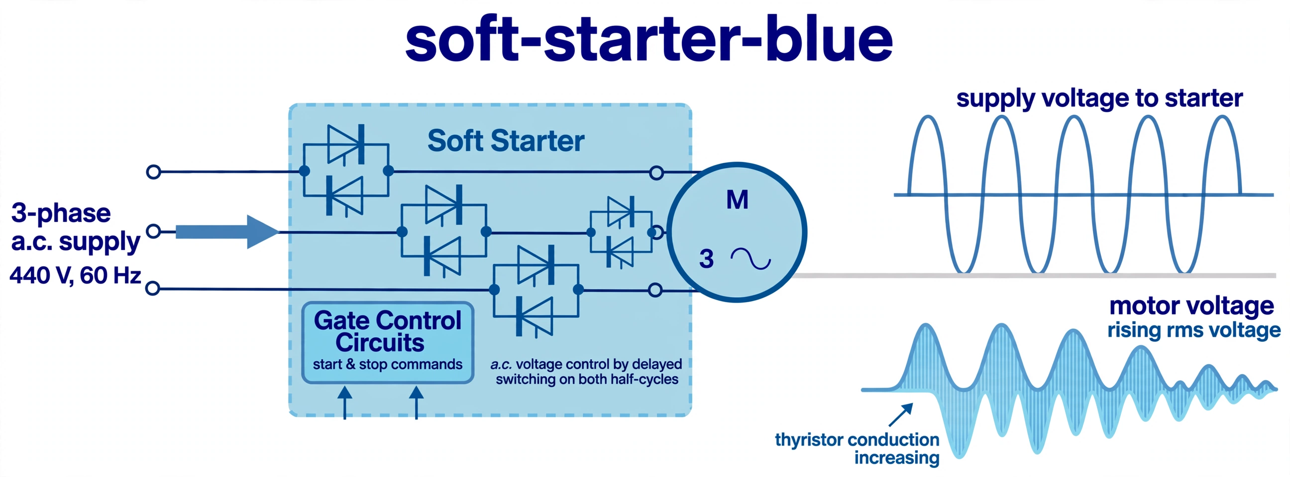
No soft starter controls speed — changing induction-motor speed means changing supply frequency. Volts manage current; hertz manages revs.