
Induction Motors — Principle, Faults & Testing
How a rotating field drags a rotor, the checklist that finds a dead motor, and the tests that prove health.
Key Principles at a Glance 5 points
- The stator builds a rotating field; the shorted rotor chases it but never catches it — that lag (slip) is what induces rotor current and torque.
- A motor that will not start is found by walking the chain in order: supply, protection, control circuit, then the motor itself — never the windings first.
- Single phasing kills differently by state: a running motor cooks on two phases, a stationary one cannot make a rotating field at all.
- Induction-motor speed obeys supply frequency (change hertz, not volts); direction obeys phase sequence; DC speed obeys armature volts and direction obeys whichever pole you flip — never both.
- Megger proves insulation at 500–1000 V DC where a multimeter cannot — minimum 1 MΩ on motors, (kV+1) MΩ on HV conductors.
1. Rotating Field, Chasing Rotor
Idea in one line: three phased windings add into one sweeping field, and the shorted cage earns its torque only by lagging behind it.
Feed the stator three phases and their magnetic fields add into one field rotating at supply speed. That sweeping field cuts the shorted rotor bars, induces current in them, and the rotor's own field drags after the stator's — always slower, because zero relative motion would mean zero induction and zero torque. The lag is slip: small at healthy load, maximum at standstill (which is exactly why starting current explodes — see starters).
Most shipboard AC motors are this squirrel-cage type: copper conductors along the rotor axis joined by end rings into a cage. Skewing staggers each bar's field-cutting so torque flows smoothly instead of jerking — while defeating slot-to-slot magnetic cogging and quieting running hum. Healthy slip runs 1–5% from no-load to full-load: a near-constant-speed machine whose widening slip under load is torque answering the call.
2. Single Phasing — One Phase Lost
Idea in one line: two phases make a pulsating field, not a rotating one — so a running motor limps and a standing motor cannot begin.
Running motor
Keeps turning on two phases but draws heavy excess current, hums louder, vibrates instead of rotating cleanly, overheats — and burns if protection is blind to it (plain heater overloads often are).
Stationary motor
Cannot start at all — two phases make a pulsating, not rotating, field. Hums, draws locked-rotor current, goes nowhere.
Causes live upstream of the windings: a blown backup fuse in one leg, an open conductor, loose wires, bad starter contacts, breaker or fuse failure, overload-relay faults. Test under load at the motor terminal box with meters on all three phases at once — phase-to-ground readings isolate the dead leg (healthy ≈ phase-to-phase ÷ 1.7). Beware the trap: pitted contacts pass meter voltage yet collapse under load current, so test loaded, then lock out and work upstream from contactors to supply.
Defence: three-phase loads deserve protection that drops all three legs together, plus dedicated single-phasing, over-current and negative-phase-sequence relays — larger motor relays arrive with single-phasing protection already fitted.
3. Fail to Start — Walk the Chain in Order
Idea in one line: a silent motor is a broken chain of supply, protection, control and winding — test it end to end, cheapest end first.
Supply: is power actually there — all three phases at the starter? A blown fuse or a dead incoming leg is the commonest silence of all.
Protection: has the overload tripped? Reset properly (off before on) and allow bi-metallic cool-down — then ask why it tripped before re-closing.
Control circuit: contactor coil burnt, contacts pitted, control relay faulty, stop switch open-circuit, start button not operating, hold-on (seal-in) contact not making so the starter drops the instant you release.
Motor itself: only now — continuity, insulation, and the burnt-winding verdict (run or rewind).
Locked-rotor current with zero cooling airflow is the harshest heating a winding ever sees. Find the break quickly, and never hold the start button in hoping it catches.
4. Speed, Direction and the Wider Family
Idea in one line: AC speed obeys frequency, AC direction obeys phase order, DC speed obeys armature volts — every control question is answered by which field you change.
| Synchronous | Induction (asynchronous) | |
|---|---|---|
| Speed | Constant on all loads — locked to supply frequency and pole count | Falls slightly with load (slip 1–5%) |
| Starting | Not self-starting — needs help to synchronism | Self-starting |
| Excitation | Requires DC field excitation | None — field induced from stator |
| Power factor | Wide range — corrects plant PF as a synchronous condenser, free-spinning on no shaft load | Lagging always |
| Duty | Constant-speed drives, precise positioning, grid generation | Almost every shipboard drive |
Wound-rotor — the heavy lifter
Rotor windings brought out to slip rings so external resistance shapes the starting torque. Lives on portable machines and small winches where breakaway torque matters most.
AC speed — frequency only
Speed follows supply frequency, so variable speed needs a 3-phase frequency converter (fast-switching power devices). Lowering volts alone only starves torque — it never commands speed.
AC direction — swap two lines
Interchange any two supply phases (R-Y-B to R-B-Y): the rotating field reverses, and the rotor follows it the other way.
DC motors (rotor and stator, field poles, commutator, brushes, fan, bearings, housing) answer differently: speed from a constant-voltage supply through a series pot or PWM chopper, direction by reversing armature or field polarity — never both (both flips cancel). And a DC motor fed with AC is a casualty in motion: low speed, brush sparking, eddy-current heat, then a burnt winding.
5. Megger Proof and the Three Fault Tests
Idea in one line: a multimeter tickles insulation, a megger stresses it — and each fault (open, earth, short) has exactly one test that exposes it.
Ritual: self-test (probes shorted ≈ zero), isolate and lock out, prove frame earth continuity first, then log phase-to-phase (U-V, V-W, W-U) and phase-to-earth. Motors pass at 1 MΩ minimum, HV conductors at (kV+1) MΩ (440 V → 1.44 MΩ, 11 kV → 12 MΩ). Below that, high-voltage machinery stays off. Moisture, dust, oil films and vibration are what drag readings down.
| Fault | Effect | Test on a removed motor |
|---|---|---|
| Open — broken conductor | No start; single-phases to burnout if running | Earth one end, probe along the wire — resistance must stay minimum throughout |
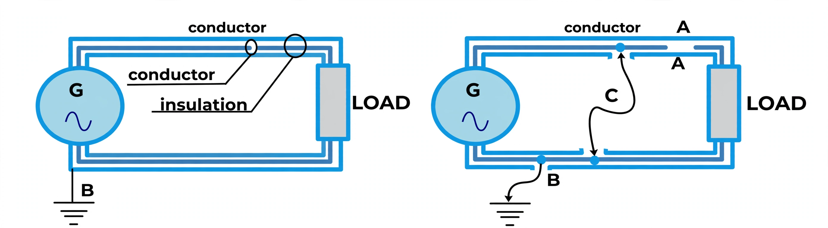
| Earth — insulation breached to hull | Current bleeds to earth, protection should lift | Open the circuit, probe wire-to-earth near the open ends — must read maximum |
| Short — insulation breached conductor-to-conductor | Massive bypass current, windings burn | Panel terminals off, all switches ON, probe across sides — anything under infinite is the fault |
Return to service — three checks before the load sees the motor: open, short, earth and IR clear; windings wired correctly (never a delta motor in star); rotation proved right before coupling the load. Dead after overhaul — check in this order, then verdict: run or rewind: terminal bars and star/delta links first, supply voltage (230/400) second, winding continuity and equal phase ohms third, IR fourth.
6. Temperature Class — Heat the Insulation May Take
Idea in one line: insulation class is a temperature promise — hotter promise, smaller frame for the same duty.
| Class | Limit | Built from |
|---|---|---|
| Y | 90 °C | Cotton, silk, paper |
| A | 105 °C | Y materials, impregnated |
| E | 120 °C | Improved organics |
| B | 130 °C | Inorganics glued — first of its kind |
| F | 155 °C | B upgraded with silicone/alkyd varnish — the marine standard |
| H | 180 °C | Inorganics in silicone resin |
| C | 180 °C+ | 100% inorganic |
Overload itself is just physics abused: slowdown draws excess current, excess current cooks windings — and temperature is what finally kills insulation, which is why heat rises and resistance falls in insulators while conductors grow more resistive with heat.