
Gas Turbines — Continuous Combustion at Sea
How compressor, combustor and turbine share one shaft, why 60% of the power never leaves, and where GTs fit on ships.
Key Principles at a Glance 5 points
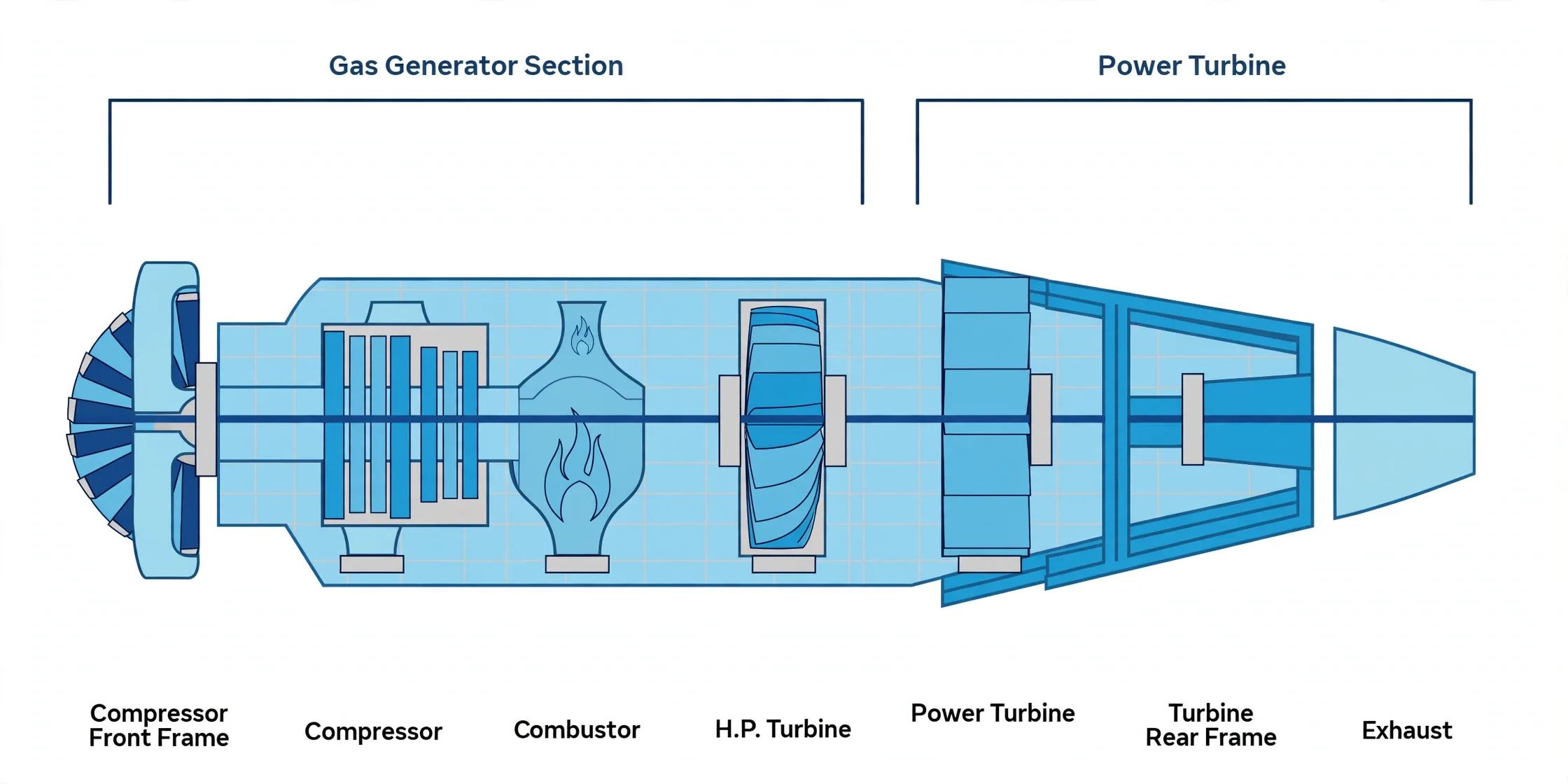
- One shaft, three jobs in continuous flow: axial compressor squeezes, annular combustor fires at constant pressure, staged turbine expands.
- 55–65% of turbine power feeds the compressor itself — only the remainder drives generator or thrust.
- Efficiency obeys two levers: pressure ratio (18:1 power, 30:1 aero) and firing temperature (blade alloy limited, coatings and cooling stretch it).
- Simple cycle stalls at 30–40%; 600 °C exhaust recovered through combined cycle reaches 55–60% at the price of slow starts and purge discipline.
- Five auxiliaries keep it alive: filtered silenced intake, safe exhaust with diverter, 60%-speed starting, dual-fuel delivery, and long-life VG 46 oil.
1. Three Sections, One Continuous Fire
Unlike reciprocating engines that fire in pulses, a gas turbine burns continuously: multistage axial compressor (rotors accelerating, stators diffusing, stage on stage to 15–20 bar), annular combustor (circumferential burners firing fuel-air at constant pressure into 1400–1500 °C gas through alloy steel), multistage turbine (fixed vanes aiming gas at moving blades, ~500–550 °C out through the diffuser). Compressor and turbine share one shaft — the turbine must first be motored to firing speed (2,000–10,000 rpm by type) on starter motor, generator-as-motor or standalone diesel before spark plugs light the continuous flame.
2. Two Levers Set Efficiency
Pressure ratio (compression work recovered as expansion work) and firing temperature (hotter top of cycle, capped by blade metallurgy) decide Brayton efficiency. Simple-cycle plants land at 30–40% with most fuel energy leaving as 600 °C exhaust — duct that exhaust into heat-recovery steam raising and the combined cycle climbs to 55–60%, trading slower starts, purge-before-light-off discipline and gentler ramp rates.
3. Steam vs Gas at Sea
| Steam turbine | Gas turbine | |
|---|---|---|
| Machine | Expander only — one Rankine step needing external boilers | Whole Brayton cycle on board: compressor, combustor, turbine |
| Output | Torque, essentially always | Torque or thrust |
| Efficiency | ~30–33% at ~550 °C steam | ~40% at ~1500 °C gas, 60%+ combined |
| Footprint | Large — boilers and exchangers alongside | Compact — air is the working fluid, everywhere available |
| Fuel | Cheap low-grade HFO in big boilers | Light gas oil, gas or dual-fire — pricier, cleaner |
| Readiness | Slow from cold | Quick, high reliability, low maintenance |
Each prime mover holds its ground:
- Slow-speed diesels own mainstream propulsion.
- Steam survives on some LNG tonnage.
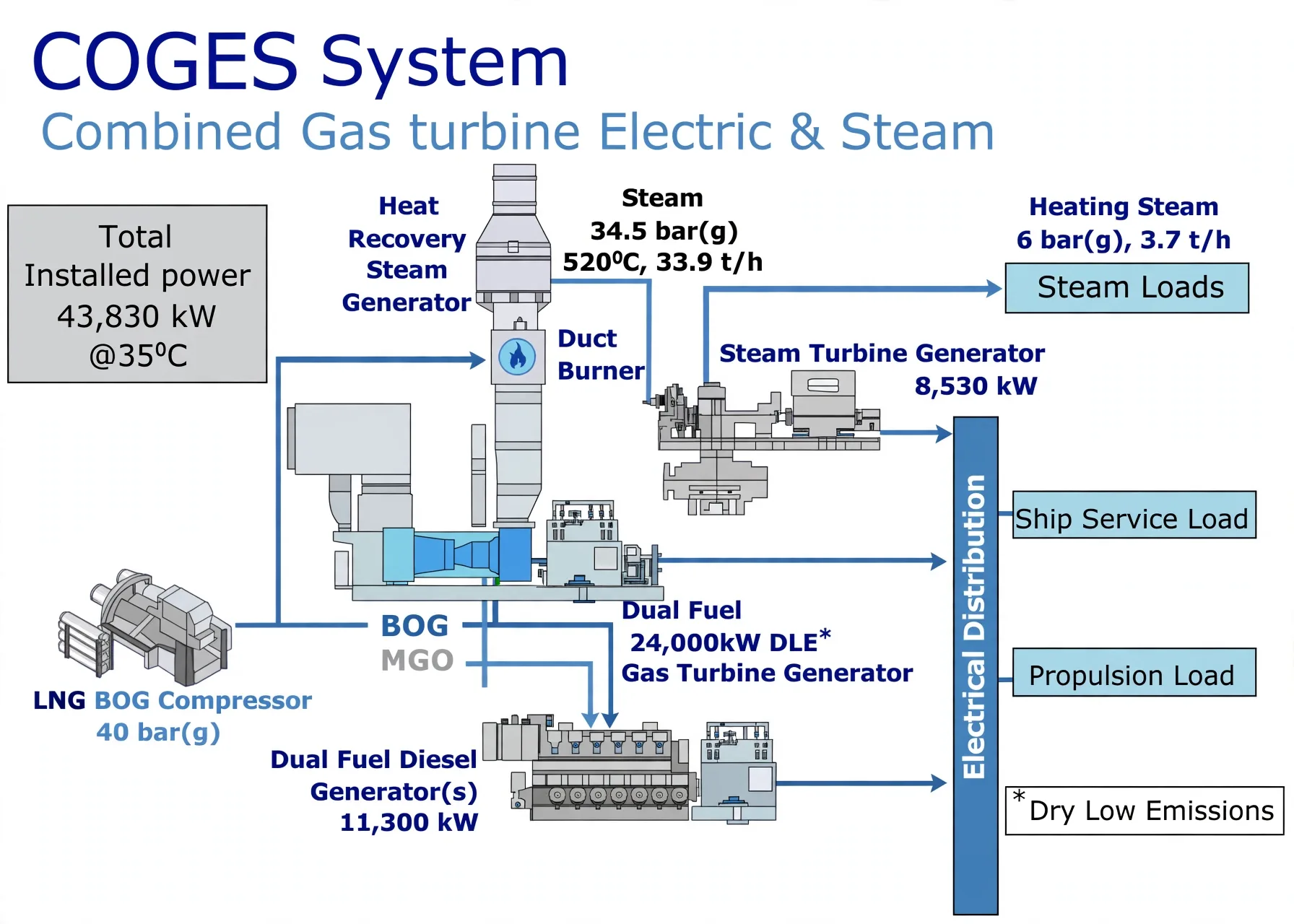
- Gas turbines return through combined packages like COGES — gas-turbine generators plus dual-fuel diesels feeding electric propulsion and steam loads off one heat-recovery backbone:
4. Five Auxiliaries That Keep It Breathing
- Intake: filters against blade fouling, silencers against duct roar, online high-pressure blade washing.
- Exhaust: tall safe stack with silencer; diverter damper to recovery boilers in combined plants.
- Starting: spin to 60% self-sustaining speed — starter motor plus torque converter, generator-as-starter, or independent diesel where no shore power exists.
- Fuel: gas, distillate or dual-fire with interlocked burner and ignition control, filtered and HP-pumped for atomisation, metered by control valve.
- Lube oil: low-viscosity VG 46 (less friction drag), 5–10% yearly make-up, multi-year life if kept clean, dry and sealed — oxidation doubles every 10 °C, so cooling and sealing are the maintenance.