
Aux Engine Valves, Valve Timing, Firing Order & Tappet Clearance
Why exhaust valves rotate in service, how 13° of overlap cleans the cylinder, and the rocking method that sets every clearance.
Key Principles at a Glance 7 points
- Inlet valves breathe cool charge; exhaust valves pass full combustion gas — so exhausts get cages, water cooling and roto-cap rotation in service.
- Exhaust heads are Nimonic alloy on Stellite seats hung by split collets in lift-out cages — cam opens against the spring, spring seals on close.
- One leaking exhaust seat starts a feedback loop — gas jet, hotter metal, distortion, wider leak — announced by fast-climbing exhaust temperature and lost power.
- The camshaft turns at half crank speed; every angle from 10° BTDC inlet opening to the 13° overlap exists so the cylinder fills, burns and empties fully.
- Firing orders stagger power end to end for crankshaft balance: 1-3-4-2, 1-5-3-6-2-4, 1-5-4-8-6-3-7-2.
- Tappet clearance is heat allowance plus guaranteed seating — excess opens late and closes early, shortage burns valves; set it by the rocking method and prove it hot.
- Lapping suits small valves to a grey ring; grinding suits large valves to a 1.5 mm foggy belt — and every trace of compound is washed off before assembly.
1. Valve Maintenance — Inlet Easy, Exhaust Hard
What the valve is made of (Clyde): exhaust heads run Nimonic alloy with Stellite-steel facings — nickel superalloy for hot strength, cobalt-chromium facing for seat hardness. The spindle hangs in the head on a split collet (two half-rings gripping a groove), and the whole exhaust assembly rides in its cage: one lift-out unit carrying valve, seat, cooling passages and rotator together.
Open and close in one breath: cam lifts pushrod, pushrod works rocker, rocker drives the spindle down against its spring — gas exits; spring returns the head to its Stellite seat as the cam passes — sealed. Rocker lubrication rides the same motion (hollow tappet screw → pushrod bowl → cam follower → valve end, watched flowing with the engine running).
Inlet — the easy life
Cool charge flows inward over the seat. No cage, no cooling passages, modest deposits — inspect, lap and refit.
Exhaust — the hard life
Full combustion gas flows outward. Caged, water-cooled and rotated in service, because a stationary hot valve distorts, leaks and burns.
Why exhaust valves rotate: rotation evens temperature around the head so sodium and vanadium salts cannot bake on one side and distort it, and it dislodges deposit build-up that would stop the valve closing and start hammering the seating faces. The mechanical rotator doing it is the roto-cap.
Overhaul pattern — every valve, every time:
Head off, spring depressed, cotters out, spindle free — then clean with a fine wire brush or buffing wheel and discard any cracked, warped or burnt valve.
Mic the stem top, centre and bottom for taper; strip carbon and varnish from the guides with a stiff spiral brush.
Rock-test each valve in its own guide, just off its seat, parallel to the rockers — the direction of greatest wear. More than slight rock condemns the guide.
Load-test every spring on the spring tester; anything off maker spec is replaced.
Seat the faces (section 2's table), wash away all compound — it is abrasive enough to wreck the engine — oil the stems and assemble.
Measure the guide-to-stem clearance as you go: worn guides and spindles are renewed, and seating faces are lapped or reconditioned only while reconditioning is still possible — then renewed.
2. Burn-Out — the Feedback Loop That Eats Exhaust Valves
Idea in one line: a leaking exhaust valve cooks itself hotter with every stroke, so the leak always grows and never heals.
Once an exhaust valve seats imperfectly, power-stroke gas jets across the faces. Local temperature rises, the material weakens and distorts, the gas jet erodes the surface wider, more gas leaks, temperature rises further. The first instrument to tell the story is the exhaust thermometer — climbing fast — with unit power falling alongside.
| Seating method | Suits | How it is done | Finished look |
|---|---|---|---|
| Lapping | Smaller four-stroke valves | Oil the stem, spread fine compound on the edge, spin the valve back and forth with the suction-cup tool like starting a fire, lifting and turning 180° to spread the paste evenly | Unbroken grey ring on valve and seat, no breaks or high spots |
| Grinding | Larger valves | Straight stem proved first (badly pitted or corroded seats will not grind out); maker machine tools and benches, paste on faces, grind on | Continuous foggy belt ≥ 1.5 mm on both faces, no breaks or scratches |
Uncontrolled repeat grinding thins the valve lid — losing strength and wearing through the hard stellite coating on exhaust valves — and with the cotter groove fixed about three-quarters up the spindle, endless grinding eventually ruins seating geometry. Wash head and valves after grinding and oil the stems on assembly.
3. Timing Angles, Overlap & Firing Order
Idea in one line: the gears phase every valve and injection event to piston position, and the camshaft takes two crank turns to play its full 720° score.
Valve timing is the relationship between crankshaft position and valve opening — set exactly, because slight error costs power and overheats, while large error stops the engine. Gear or chain drive from crankshaft to camshaft phases everything; the camshaft wheel carries twice the teeth, so it turns at half crank speed: one valve cycle per two crank revolutions. Keyed wheels fit their shafts one way only — but they can still be meshed wrongly to each other, so timing is proved against maker marks (timing cover off) after any gear, chain or camshaft disturbance.
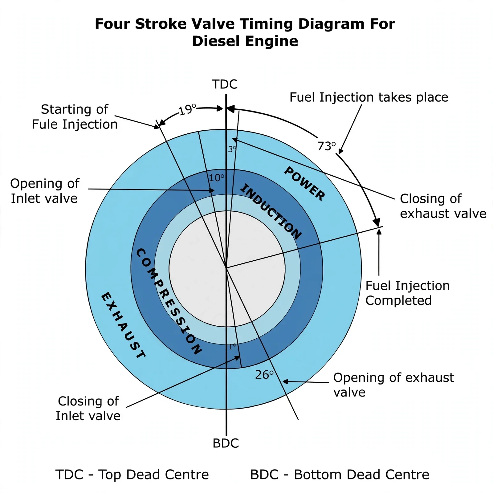
The induction stroke starts with the inlet opening 10° before top dead centre; air is drawn in as the piston descends and trapped when the inlet closes near bottom dead centre. Rising-piston compression heats the charge until injection begins 19° before top dead centre and continues to 73° after — the hot air fires the fuel and expansion drives the power stroke. Exhaust opens 26° before bottom dead centre and blows down while the piston rises; near top dead centre the inlet re-opens, and both valves stand open together across the 13° overlap (10° before to 3° after top dead centre) so incoming air scours out the last exhaust and every cycle starts fully charged.
| Event | Angle | Why there |
|---|---|---|
| Inlet opens | 10° BTDC | Head-start on filling; doubles as overlap scavenging |
| Inlet closes | 1° ABDC | Traps the full charge once the piston turns upward |
| Injection | 19° BTDC → 73° ATDC | Fuel lands in hot compressed air and burns across dead centre |
| Exhaust opens | 26° BBDC | Early blow-down empties the cylinder before the stroke ends |
| Exhaust closes | 3° ATDC | Closes the overlap once fresh air has swept the cylinder |
Firing order staggers power pulses end to end so crankshaft thrust balances: cylinders number from the front (inboard end) to the back (propeller-shaft end), firing first one end then the other. Fours fire 1-3-4-2, sixes 1-5-3-6-2-4, vee-eights 1-5-4-8-6-3-7-2 — straight-line blocks or compact vee arrangements holding the same logic.
4. Tappet Clearance — Heat Allowance That Times the Valve
Idea in one line: the rocker only rests on the valve, and the gap between them is what lets a hot valve still shut — while quietly shifting when it opens.
Tappet clearance (valve lash) is the gap between rocker arm and valve tip. There is no rigid link — the rocker just sits on the valve while pushrods work the arm — and because valve and gear grow with heat, the gap shrinks in service. Correct clearance does two jobs: absorbs stem growth and guarantees positive closing. Geometry then ties clearance to timing: excess clearance opens late and closes early (plus noise and wear); shortage opens early and closes late, and at zero the valve never seats — compression leaks, faces burn, and in the extreme the piston strikes the valve, bending stems or worse. Exhaust clearances run larger than inlet (hotter valves), typically 0.3–1.5 mm, drifting about 0.128 mm between cold and running temperature.
When to check: with timing proved correct — and whenever the head is overhauled, valves reconditioned or renewed, the valve gear disturbed, or the head re-tightened after its initial run-in. Clearance is set by screw and locknut in the rocker end, measured with a feeler between stem and arm on a fully closed valve — go/no-go style, thinner gauge passes while the next size up refuses. Cold setting stands alone; if only a hot figure is published and the gear was disturbed cold, set cold first, then recheck at full operating temperature before any valve cools — running clearance closes up under load.
Rocking method (six-cylinder 1-5-3-6-2-4):
Governors to idle (stop lever secured if fitted), covers wiped and lifted, then bar the engine round in running direction.
Watch for the rock: on one cylinder the exhaust rocker closes while the inlet rocker opens — that piston is ending exhaust and starting induction, pushrods tight. Its 180° partner then rests at compression TDC with both valves shut and pushrods free — set both its clearances there.
Walk the firing order: rock 6 → set 1, rock 2 → set 5, rock 4 → set 3, rock 1 → set 6, rock 5 → set 2, rock 3 → set 4.
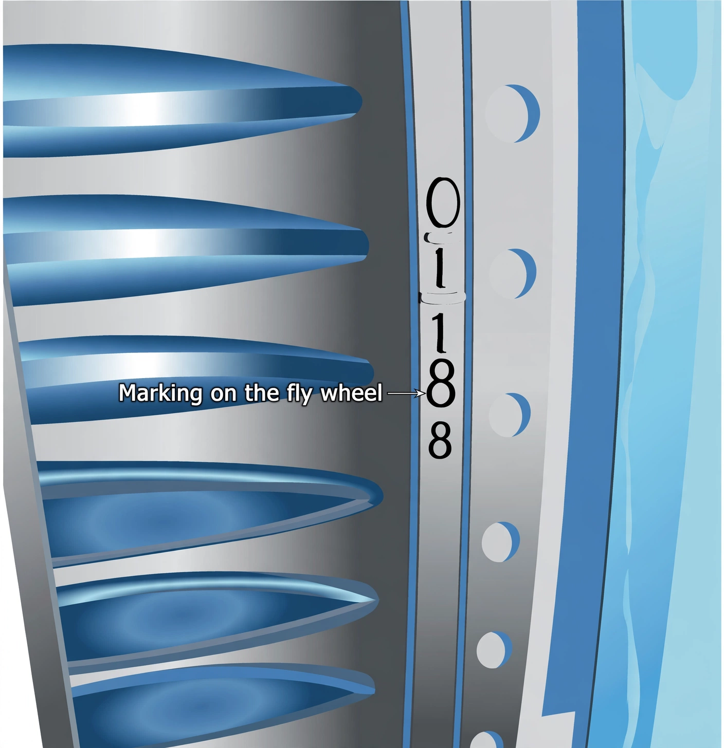
Confirm each setting against the flywheel's TDC unit marks, lock the nuts, and re-prove every gap after locking.
Rocker lubrication rides the same motion: cam lifts pushrod, pushrod works rocker, rocker opens the valve against its spring — while oil fed from the rocker shaft through a hollow tappet screw fills the pushrod's bowl seat, overflows down the rod to the cam follower, and reaches the valve-and-spring assembly through a hole drilled along the rocker's valve end. Watch it flowing with the engine running — flow rate shifts with clearances, and a starved rocker points at blocked feed filters. Shafts, bushes and bearings are gauged at overhaul and renewed past limits. For the companion fuel-side story — pumps, injectors and the 5° that sets the fire — see Aux Boilers, Liner Calibration & Fuel Pump Timing.