
Compressor Safety Devices, Unloader & Air Receivers
Which device saves which failure, why the unloader drains more than load, and what lives on an air bottle.
Key Principles at a Glance 6 points
- Protection is layered: relief valves vent excess stage pressure, bursting discs sacrifice themselves when cooler tubes leak into the jacket, fusible plugs dump heat-soaked air at 120 °C.
- Trips stop the machine before damage compounds: low lube-oil pressure, high cooling-water temperature, cooling-water no-flow, and motor overload.
- The unloader serves starting current, oily-moisture draining and intermittent condensate purging — timer-driven through pneumatic or solenoid valves.
- Two receivers of about equal size hold twelve consecutive ahead-and-astern starts; every mounting from filling valve to whistle valve has exactly one job.
- A receiver is an unfired pressure vessel and an enclosed space: permit, drain, blank every entry, inspect shell, welds and coatings, recoat and leak-test.
- Read stage pressures as a pair: low discharge means leakage or starvation on that stage, high discharge means the next stage is refusing the air.
1. Three Safeties, Three Different Failures
One idea organises every safety on a compressor: each device answers one failure that nothing else can. Learn them as failure → device, not as a list — over-pressure vents through a relief valve, jacket flooding bursts a disc, outside fire melts a plug.
Relief valve — excess stage pressure
Fitted between first stage and intercooler and between second stage and aftercooler; lifting pressure rises stage by stage. Vents over-pressure and reseats. Overhaul on hours and prove opening pressure on a hydraulic tester.
Bursting disc — cooler tubes leaking into the jacket
Copper disc in the inter/after-cooler water space with an O-ring seal and securing flange. Bursts at a set safe pressure so the casing and crew survive. Renew only with identical material and thickness; clean dirt from the space and the O-ring seat at maintenance.
Fusible plug — external heat, 120 °C
On the discharge side and on receivers. A nearby fire melts the core and dumps the air before heat weakens the vessel. Melting is the design — it is single-use by definition.
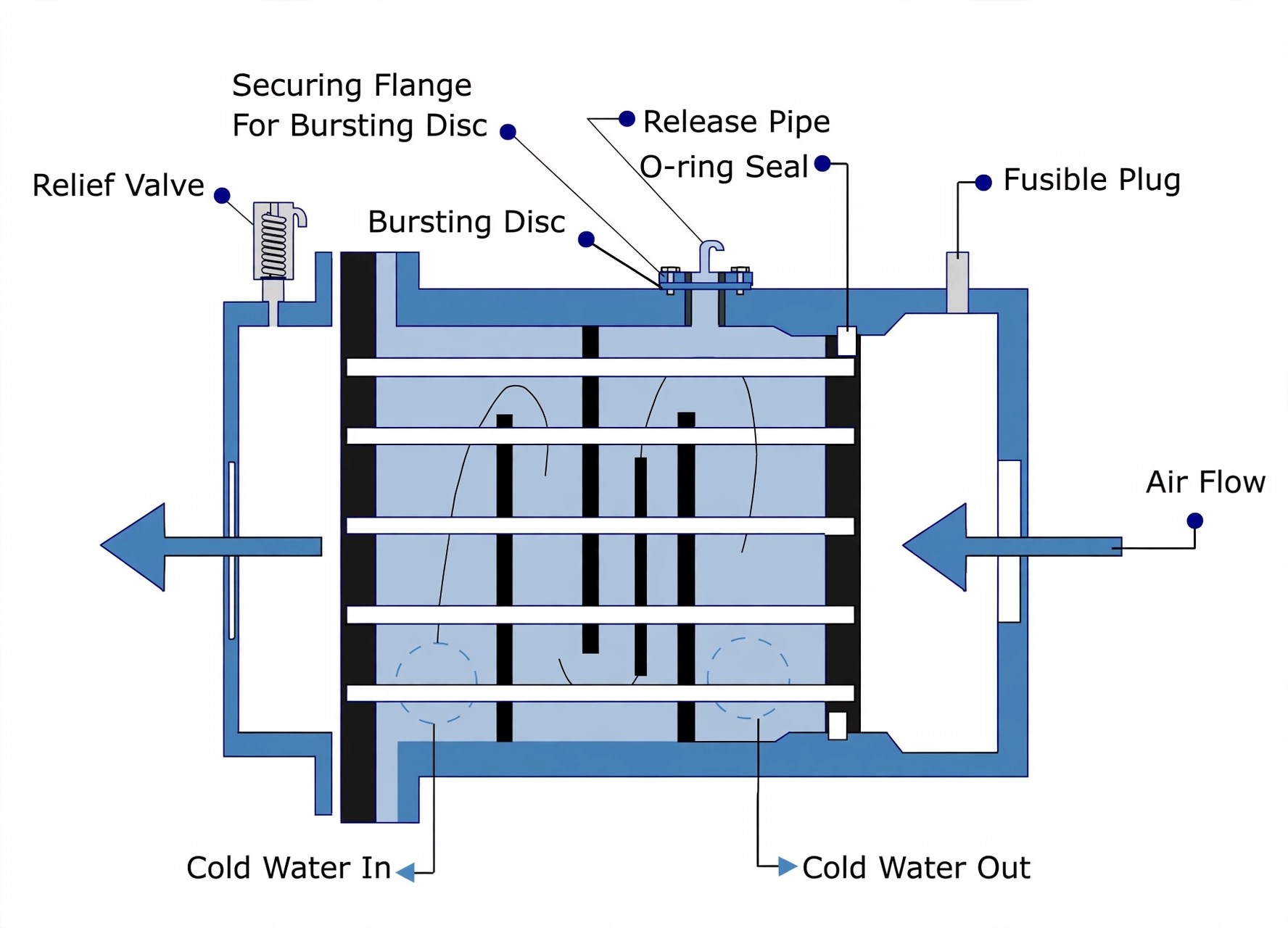
The trip family stops the compressor before damage compounds — each trip guards one failure mode:
Lube-oil low-pressure trip
Alarms first, then trips — protects bearings and crankshaft from running dry.
Cooling-water high-temperature trip
Acts when choked intercoolers or weak water flow overheat the machine, before heat damages it.
Water no-flow trip
A dead attached pump or choked cooler means seizure — the trip stops the unit first.
Motor overload trip
Covers an unloader shut at start, a seized bearing, or broken rings — anything that spikes current and could burn out the motor.
Standard alarm set to know by heart: high air temperature, high cooling-water temperature, low lube-oil pressure.
2. The Unloader Does Three Jobs
One idea explains the unloader: engine-room intake air is wet and oily, and compression concentrates that mixture into something that attacks the machine. Unloading is not just easier starting — it is current control, chemistry control, and housekeeping in one valve.
Limit starting current — start with the unloader open, close it to load once running. Starting against full discharge pressure spikes current and can damage the motor outright.
Drain the oily-moisture mix — engine-room air is wet and oily; compression shrinks its volume and concentrates that mixture onto pistons and valves. Unload at stopping and before the next start so the machine never sits in its own condensate.
Purge condensed water mid-service — unload intermittently on the timer so separated water leaves with the air instead of slugging downstream into cylinders and bottles.
3. Symptom → Cause Troubleshooting
One idea reads every gauge fault: pressures tell you who is leaking and who is refusing. Low discharge on a stage means that stage is leaking or starved; high discharge means the next stage downstream is refusing the air. Check in the order given — cheap and external first, internal last.
| Symptom | Check in this order |
|---|---|
| Lube-oil pressure low | Oil level low → suction strainer choked → pipe leaks → wrong oil grade → gear pump faulty → gauge faulty → bearing clearances opened up. |
| Cooling-water temperature high | Valves closed? → piping blocked → pump belt loose or broken → pump faulty → no flow → expansion-tank level low. |
| Noisy running | Bearings worn → crankshaft end play high → discharge pressure high → poor foundation → bumping clearance small → rings/liner worn (piston slap) → valves badly seated, broken or faulty. |
| 1st-stage discharge low | 1st-stage suction valve not closing (leaks on compression) or not opening fully (starves charge) → discharge valve opening prematurely or wrong soft springs → intake filter fouled → piston-ring leakage. |
| 1st-stage discharge high | 2nd-stage suction valve not holding, passing HP air back to the intercooler → intercooler tubes choked. |
| 2nd-stage discharge low | Piston-ring leakage → 2nd-stage suction valve escaping → 2nd-stage discharge valve leaking or opening early on wrong springs. |
| 2nd-stage discharge high | Aftercooler or discharge-valve obstruction → bottle pressure already high → over-stiff discharge springs. |
4. The Air Receiver — a Pressure Vessel With Twelve Starts Inside
One idea defines the receiver: it is stored manoeuvring energy, sized by law, built like a boiler. Main receivers are unfired pressure vessels — mild-steel boiler plate shell with dished welded ends, stress-relieved after construction by a slow soak near 580 °C. Rules demand two receivers of about equal size holding twelve consecutive main-engine starts, ahead and astern.
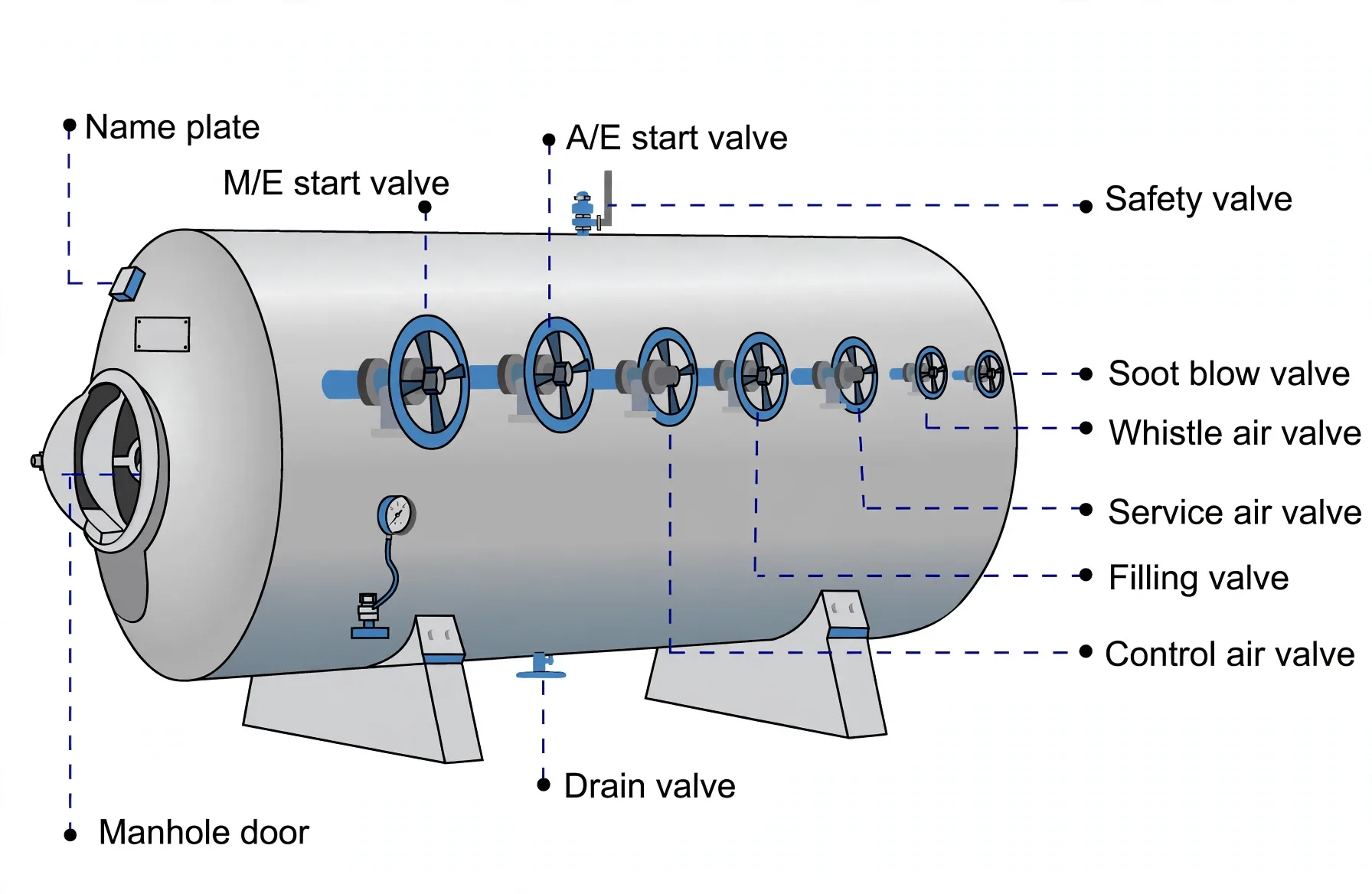
Mountings, each with one job:
| Mounting | Job |
|---|---|
| Manhole door | Elliptical, hinged inside — bottle pressure itself holds it shut, studs only locate it. |
| Nameplate | States maximum and working pressures with the maker name. |
| Main and aux starting-air stop valves | Feed the main-engine and auxiliary-engine starting-air manifolds. |
| Safety valve | Mandatory on a pressure vessel — vents excess bottle pressure beyond safe working limits. |
| Control-air, service-air, soot-blow and whistle valves | Supply their reducing stations and services at 7 bar from the 30-bar bottle. |
| Filling valve | Non-return from the compressor discharge into the bottle — flow in, never back. |
| Drain valve | Drains water and oil sludge from the bottom where both collect. |
5. Internal Inspection — Enclosed Space, No Shortcuts
One idea keeps bottle entry safe: pressure can return through any forgotten connection, so the bottle is isolated like a life depends on it — because one does. The hunt inside is for corrosion, pitting and weld cracking — worst where water collects and where coatings are already damaged.
Permit and isolate: obtain the work permit, drain the bottle, blank every possible air entry including cross-connections to other receivers — because interconnections can silently re-pressurise the space.
Enter as an enclosed space: follow the checklist throughout, with personnel stationed outside while anyone is inside.
Inspect three areas, each for its own defect: shell and water-trap regions for corrosion and coating damage; every weld including mounting welds for stress cracking; manhole-door fit.
Restore: recoat internally with a clear protective coating, refit the door (pressure will hold it shut in service), leak-test before return to service.