
Reciprocating Air Compressors — Operation & Overhaul
Why starting air needs two stages, how to start unloaded every time, and the full strip-down down to the crankshaft.
Key Principles at a Glance 6 points
- Ships carry two air pressures: 30 bar high pressure for starting main and auxiliary engines, 7 bar low pressure for control and general service.
- Compression is split into two stages with intercooling because a single stage beyond about 1:7 runs hot enough to destroy efficiency and approach oil flash point.
- Always start and stop the compressor unloaded, drain condensate during the run, and monitor pressures, temperatures, oil and noise throughout.
- Hour-based routines run from 250-hour filter and valve checks through 500-hour oil changes to 4000-hour piston, cooler and motor overhaul.
- Bumping clearance near 0.5 mm (0.5–1% of bore) decides volumetric efficiency — measure with lead wire and adjust with shims.
- Suction valve springs are softer than discharge springs and the two valves must never be interchanged — a swap over-pressurises the chamber.
1. Two Pressures, Two Stages — Why the Plant Looks This Way
One idea runs this whole chapter: compressing air heats it, and hot air fights back — it resists further compression, carries less charge per stroke, and pushes lubricating oil toward its flash point. Every design choice below exists to keep that heat under control.
Compressed air does far more than start engines — automation and control, hydrophore pressurising, sewage-plant aeration, boiler soot blowing, fog horn and whistle, lifeboat air motors, pneumatic pumps and hand tools, plus general cleaning and painting. Because starting and control need very different pressures, the plant splits in two:
Study the manual of the particular machine plus the SMS routine before touching anything — running-hour history, recorded clearances, and maker tolerances are the baseline every overhaul builds on.
2. Starting, Running, Stopping — the Unloaded Discipline
One idea governs operation: a compressor must never fight full discharge pressure at standstill or trap wet air at shutdown. Starting loaded spikes motor current; stopping loaded leaves hot moisture inside to attack the next start. The whole procedure is built around loading only mid-run.
Pre-start checks — sump and lubricator oil level correct; intake filter clean; cooling-water pressure correct with every line valve open; gauge cocks cracked slightly open so needle flutter cannot hammer the gauges; relief valves hand-tested on their levers where fitted.
Bar it over a few revolutions with the turning bar — it must move freely with no binding, which proves no liquid lock, no dropped part, no seized bearing.
Start unloaded, then load — unloader open (or drains open), and only close drains to load once running. In automatic mode the machine cuts in and out on air consumption by itself.
Drain condensate during the run — water vapour in intake air condenses as air is compressed and cooled; periodic draining keeps it out of the cylinders.
Unload before stopping to leave the machine dry and ready for the next start. Monitor pressures, temperatures, oil, and noise throughout the run.
3. Hour-Based Routines, Filters and Oil
One idea sets the maintenance rhythm: dirt and degraded oil kill compressors long before parts wear out — choked filters starve flow and overheat delivery air, tired oil stops protecting bearings. So the schedule is really a filter-and-oil schedule with deeper strip-downs layered on top.
| Hours | Work |
|---|---|
| 250 | Clean air filter; remove, inspect and overhaul suction/discharge valves; check cooling-water pump drive-belt tension (belt dressing protects and cuts slip); prove unloader operation; dismantle and renew rubber seals and gaskets. |
| 500 | Change crankcase oil and clean sump; clean lube-oil filter; renew suction and discharge valves with overhauled spares. |
| 1000 | Crankcase inspection with main and big-end bearing inspection; relief-valve overhaul; full oil replacement with crankcase flush. |
| 4000 | Piston and big-end overhaul with ring renewal; intercooler cleaning; motor overhaul. |
Air filter — 250 h
Isolate, unclip, remove the element. Dry type is mostly disposable; wet viscous-impingement type is chemically cleaned and rinsed with fresh water, then blown off. Engine-room air is dirty — filtration protects liner surfaces from abrasion.
Lube-oil filters
Two filters: a screen-type suction strainer (remove, wash in clean kerosene, blow off with air, refit) and a discharge fine cartridge (use-and-throw — renew it). Falling oil pressure is the signal to clean.
Oil replacement
Isolate, remove the drain plug and collect the oil. Read it before discarding it — debris or metal particles mean investigate and rectify first. Rinse with clean kerosene, mop dry with lint-free cotton (no fluffy rags), flush with maker-grade oil, refit the plug without over-tightening, fill to the mark. Check connecting-rod play while the crankcase is open.
Survey sense: unless there is a major failure, leave a big overhaul until berthing — a reversible fixed-pitch plant needs huge air reserves for manoeuvring. Keep survey papers ready: previous reports, running hours since last survey, PMS records, recorded clearances and maker tolerances.
4. Strip-Down Sequence — Top Down to the Crankshaft
One idea controls every strip-down: prove zero energy first, then work top-down so each layer exposes the next. Isolate electrically (control-room and local breakers off, permit, fuses out, lockout, warning boards, off auto-start and priority) and mechanically (cooling water shut, HP discharge shut, cooler drains opened to prove no trapped pressure). For a full unit lift: disconnect junction-box leads and earth, free all pipework without spilling oil, open relief valves and cooler drains by hand, unbolt foundations and trolley the unit clear, then clean it externally.
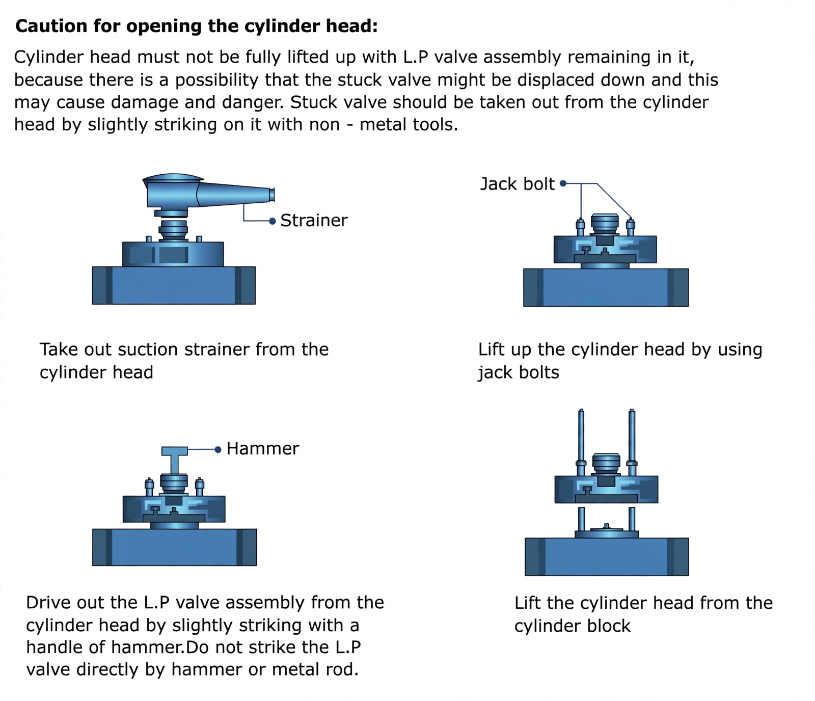
Cylinder head: remove air, cooling-water, delivery and suction-filter connections, slacken nuts with the maker tool, lift with correct lifting gear. Never fully lift with the LP valve assembly still seated — a stuck valve can drop; drive stuck valves out with non-metal tools only, never strike them directly. Decarbonise, inspect for damage, and pressure-test after reassembly.
Valves to the workshop for overhaul (next sections) — first/second stage, suction and discharge.
Piston, rings and pin: remove circlips, gudgeon pin and top-end bearing with proper tools; take rings off with an expander. Clean and decarbonise, then gauge ring grooves, pin diameter and clearances, and record bumping clearance. Side clearance and butt clearance (ring levelled in its bore) are both checked with a feeler gauge — renew over-limit sets. The pin must be a push fit in the rod bore; renew a shaking small-end bush.
Cylinders and connecting rods: check piston-to-liner clearance at right angles at top, middle and bottom of the liner; measure the piston skirt across the gudgeon-pin bore and the HP cylinder dimensions — renew beyond limits. Split the rod caps through the crankcase door, fit new big-end bearings and small-end bushes with oil holes aligned and fully open, and check the fit on the crankshaft.
Bracket and crankshaft: unbolt the motor bracket, tilt the crankcase onto its pump face, remove the seal housing, lift the bracket then the crankshaft out. Blow every crankshaft oil hole clear with compressed air; never remove balance weights (reassembly unbalance). Check main journal bore sizes against condemning limits.
Oil pump: strip, clean, inspect, renew worn parts. There must be zero rotor end play (lap the pump-body outer face if excessive) yet enough rotor-to-cover clearance that rotors never stick; the inner rotor must move freely inside the outer.
5. Bumping Clearance — the Half-Millimetre That Decides Efficiency
One idea makes this clearance matter: the piston crown must stop just short of the cover, because the gap left behind is dead air every stroke must re-expand. Too much gap wastes suction on stale air; too little gap lets the piston kiss the cover. About 0.5 mm on a two-stage main compressor — generally 0.5–1% of bore — is the sweet spot.
Measure: valves out, lead wire (or squeezable plastic) on the piston centre under the cover, bar the flywheel by hand, remove and mic the crushed wire, compare with the maker figure.
Diagnose: high clearance means bearing wear-down is stealing suction; low clearance means excess crankpin or main-bearing play is lifting the piston — unloaded, with no air cushion, the uplift bangs the cover on the upstroke.
Adjust and record: add or remove shims at head-to-block or between big-end halves; always recheck after a major overhaul and log the reading for the survey file.
One or two lead-wire attempts only. Excess wire strains cover studs and the piston itself.
6. Plate Valves — Overhaul Without Mixing Them Up
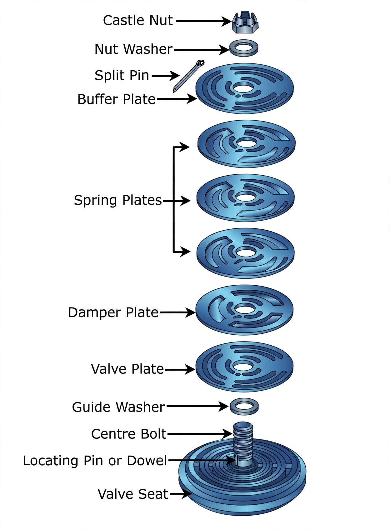
One idea keeps valves safe: suction and discharge plates look alike but breathe oppositely — suction springs are softer than discharge springs. Fit a soft spring on discharge duty, or swap the valves outright, and the chamber over-pressurises toward explosion. LP stages may use separate suction/discharge valves or one combined valve; HP stages use separate valves.
Isolate and remove: electrically isolated with fuses out and a chief-engineer permit; take first- and second-stage suction and discharge valves to the workshop with their special tools.
Strip and clean: split pin out, castle nut off, dismantle everything — soak in kerosene or clean diesel, soft brush only (copper scraper for hard deposits). Suction valves open clean, discharge valves carbonised — that contrast is normal. If any part is broken, locate every fragment before it reaches the compression space.
Inspect: check plates, seats, spring plates and locating pins for pitting, wear, distortion and fatigue cracks. Cracked or fatigued plates are renewed — never flipped and reused, never reconditioned. Seats go to skilled hands only; a damaged seating face means a new seat. Fit spring plates correctly on the locating pin, torque castle nuts right, fit split pins.
Lap and prove: lap plate and seat separately on a surface plate with fine then extra-fine paste so each face is flat on its own datum; wash in diesel and blow dry so no grit survives; assemble lapped faces together so the proven pair mates as tested; check movement with a soft wooden stick so the plate lifts freely without bruising the fresh lap.
Leak-test and refit: flood the space above the plate with water or kerosene — no level drop after minutes means fit for service. Refit suction to suction and discharge to discharge, checking every part number against the manual.
Return to service — rebuild, prove and load in this order, because each step protects the next:
New head gasket, torque-sequence tightening, then pressure-test the head — so the joint seals before any load reaches it.
New rings with butt and axial clearances checked, gaps staggered to block blow-by and oil leak paths, TOP marks up, pre-lubricated — so each ring seals, expands and beds in.
Verify bumping clearance and bar the flywheel free — so the piston cannot kiss the cover on the first stroke.
Torque all nuts to maker settings with new locking devices — so vibration cannot back anything off.
Clean or renew crankcase suction filter, refill with new oil, renew lube-oil and air filters, open cooling water and check leak-free — so bearings and jackets are protected from the first revolution.
Prime the lube pump by continuous hand-turning — so oil reaches bearings before load arrives.
First run unloaded watching amperes and noise, then load and check for bearing overheating — so tight or starved parts show up before damage compounds.
Time the empty-to-full bottle fill, log every clearance and spare, raise spares requisitions, update the PMS running hours — so the next overhaul starts from measured history.