
Instruments & Safety Systems
Meters that stress insulation, sensors that read heat, barriers that starve sparks — and the rescue drill when current finds a human.
Key Principles at a Glance 5 points
- Meggers torque-prove insulation: voltage-driven deflection against current-driven restraint — infinity means open, zero means shorted.
- Thermocouples turn junction temperature into microvolts via Seebeck (with Peltier and Thomson behind it); K rules general duty, E shouts loudest, J quits at iron's Curie point.
- Earth faults announce on the alarm relay, then get hunted section by section with the plant alive — leakage (capacitive whisper) is not yet a fault (bolted contact).
- Hazardous areas grade protection four ways: Ex-d contains the explosion, Ex-e removes the spark, Ex-p keeps gas out with pressure, Ex-i starves the circuit below ignition.
- Charging batteries breathe hydrogen, so the room gets spark-proof lighting, ventilation and no naked flames — and the human body gets a 50 V working limit with rescue rehearsed, not improvised.
1. Megger — Torque as a Test Instrument
Idea in one line: one coil pulls with test voltage, the other restrains with leakage current — the pointer settles where insulation truth lives.
Hand-cranked (armature in permanent field) or battery-electronic, a megger pits voltage torque against current torque on one pointer: open circuit swings full to infinity, dead short drags it to zero.
Ritual: prove the meter shorted, ground both terminals separately to prove earths, then probe conductors — below minimum, high-voltage machinery stays off. Multimeters cannot substitute: 3 V tickles insulation that 500 V DC breaks down, and only the breakdown voltage tells the truth.
2. Thermocouple — Heat Into Microvolts
Idea in one line: a temperature gradient across joined dissimilar metals is a tiny voltage source — read the microvolts, look up the degrees.
Three thermoelectric effects sit behind every thermocouple:
Seebeck
Welded dissimilar wires develop volts across a temperature gradient.
Peltier
Push current instead and junctions heat or cool.
Thomson
Current along a gradient absorbs or releases heat.
Tables turn microvolts back into degrees:
| Type | Build & sensitivity | Range & duty |
|---|---|---|
| K | Chromel-alumel, ~41 µV/°C | −200 to +1350 °C, general duty |
| E | 68 µV/°C, cryogenic-friendly, non-magnetic | Faint signals |
| J | Iron-constantan, ~50 µV/°C | −40 to +750 °C, stopping where iron's 770 °C Curie point bends its curve |
3. Earth Faults — Alarm, Then Hunt
Idea in one line: the relay watches for current going where no wire runs — then you halve the plant until one feeder stands accused.
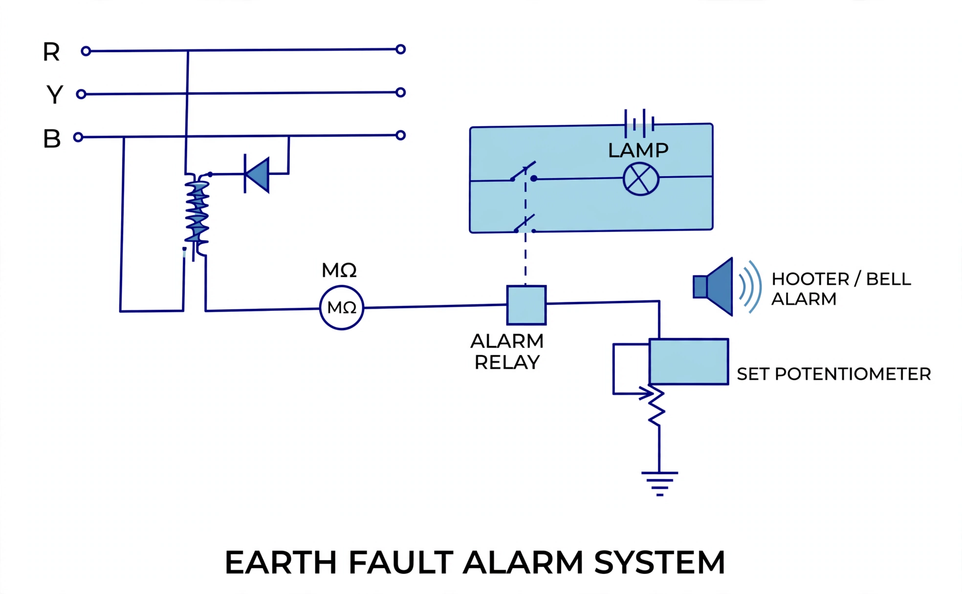
Fault
A phase touching neutral (earthed plant) or hull potential (insulated plant).
Leakage
Capacitive or high-resistance bleed is mere leakage — not yet a fault.
Trace it live by elimination — open and close breakers carefully (mind essential loads) until the alarm clears, starting where faults breed: galley and laundry first.
Insulated neutrals
Survive first faults at equal potential (alarm only).
Earthed neutrals
Pass fault amps that trip gear instead — which is exactly why HV plants earth: one fault must kill the circuit, not smoulder into two.
One transformer subtlety: the 220 V distribution board needs its own earth lamps — the step-down air gap means 440 V lamps cannot see a 220 V earth.
4. Detectors & the Flicker Trap
Idea in one line: match the sensor to the fire's stage — ions for flame, scatter for smoulder, melt or climb-rate for heat.
Smoke
- Ionization chambers feel flaming ions first.
- Optical heads see smouldering scatter first.
- Dual heads cover both.
Heat
- Fixed-temperature eutectic links melt at their set point.
- Rate-of-rise heads fire on climb speed.
Freezes or reverses rotating machinery under single-phase flicker. Defeat it with full three-phase lighting or high-frequency drivers, never with warnings alone.
5. Ex Family — Four Ways to Deny an Ignition
Idea in one line: every Ex type breaks the same triangle (gas + spark + heat) at a different corner — contain it, remove it, exclude it, or starve it.
| Type | Principle | Shipboard note |
|---|---|---|
| Ex-d flameproof enclosure | Withstands an internal gas explosion and cools the flame path before it reaches outside air | Battery lockers carry this rating |
| Ex-e increased safety | Eliminates open sparking — built without switching contacts | Terminals and lighting fittings |
| Ex-p pressurization | Clean-air pressure keeps surrounding gas from ever entering | Analyser and control housings |
| Ex-i intrinsically safe | Circuits cannot release ignition heat — capped below about 30 V, 50 mA | Handheld radios, sensors on barriers |
Intrinsic safety in practice means Zener clamps or galvanic isolators on every wire entering the hazardous area — the barrier, not the device, guarantees the energy ceiling.
6. Battery Room — Hydrogen Sets the Rules
Idea in one line: charging breathes out hydrogen, so the room is ventilated, spark-free and flame-free by design — every fitting and every habit obeys the gas.
Gas discipline
Ventilate continuously, never smoke or bring naked lights near, and fit spark-proof lighting — hydrogen needs only a spark to remind you it was there.
Terminal discipline
Never bridge positive to negative — the flashover is violent. Disconnect negative first, reconnect it last.
Upkeep rhythm
Weekly cell voltages and hydrometer specific gravity, terminals greased against corrosion, occasional load tests, cells kept covered (distilled water top-up), batteries dry, clean, trickle-held, terminals smeared.
7. Shock — Limits, Precautions and Rescue
Idea in one line: current kills, not voltage — so work keeps voltage below the body's danger line, and rescue buys back breath within seconds.
Safe voltage normally sits at 50 V, shifting with body resistance and path — insulating boots or a mat raise the survivable line. Shock as low as 15 mA AC or DC can kill. And the welding paradox resolves in one phrase: the whole hull sits at the same potential, so with no potential difference across the body there is no shock — even beside kilovolt ignition gear that must break down an air gap to throw its spark.
Before touching anything electrical: switch off power, wear protective clothing and safety shoes, hang the no-switch board, stand on a rubber mat, strip off rings and bracelets, use insulated tools, prove dead with a voltmeter — and prove the voltmeter itself on a known supply. Keep one equipped person standing by, inform authority, and hold a proper work permit.
Raise the alarm — shout it before you touch anything.
Isolate the current — switch off. If impossible, drag or push the victim clear with something non-conductive, never bare hands on victim or source.
Resuscitate at once — if breathing is feeble or stopped, begin artificial respiration immediately and check heartbeat and pulse. Started at once, ~70% recover; three minutes late, ~20%.
Never enter a space breathing 19% oxygen or below — test the air, ventilate, and follow enclosed-space entry discipline before any rescue inside.
8. Barriers, Hull Current & Last-Resort Power
Idea in one line: cap the energy a spark may spend, spend hull current instead of hull steel, and keep one power source that never depends on the main bus.
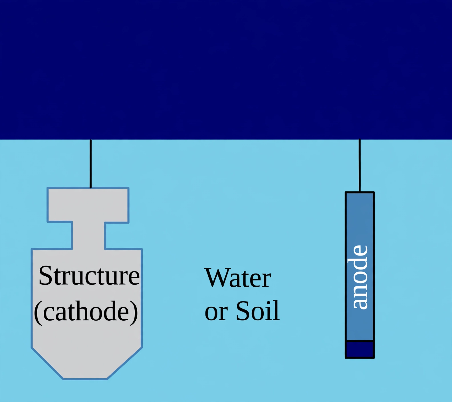
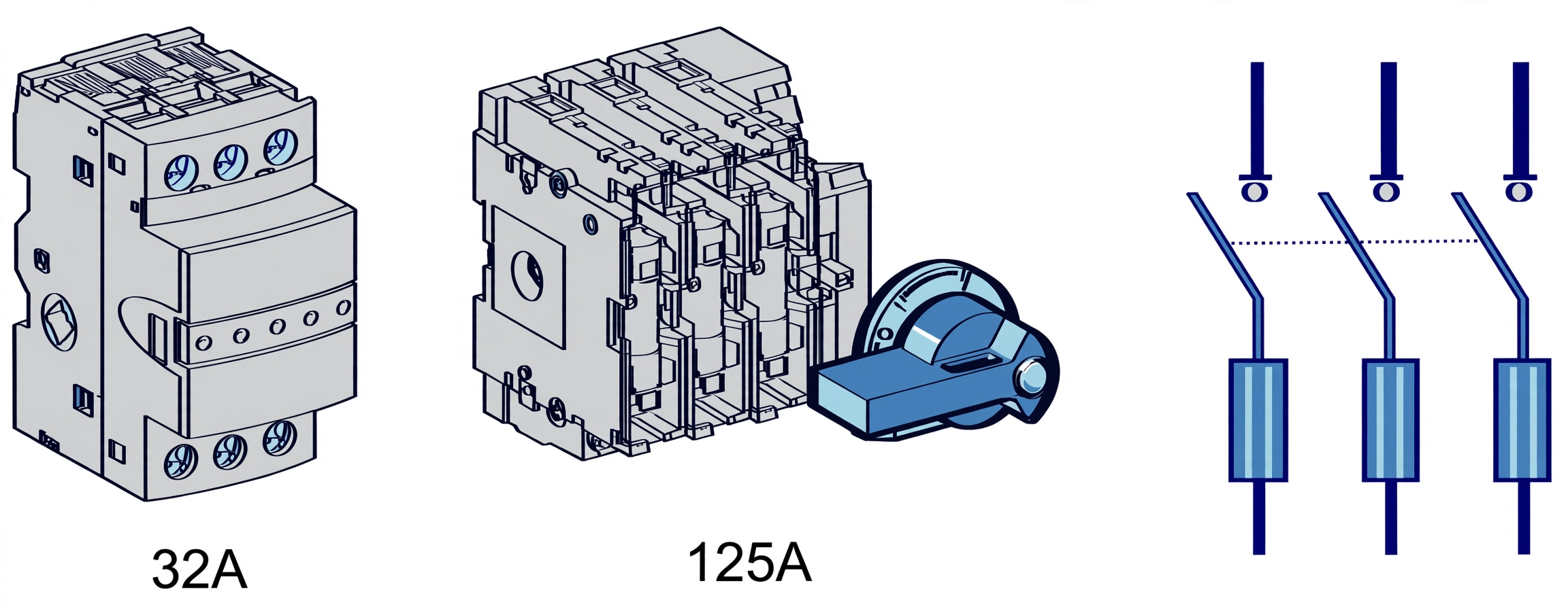
Intrinsic safety keeps hazardous-area energy below ignition — Zener clamps or galvanic isolators on every wire in (walkie-talkies live here). ICCP makes the whole hull a cathode: transformer-rectifier current flows off graphite/silicon-iron/platinised-titanium anodes through seawater onto steel, steered by a passive reference cell, auto or manual — fewer, harder-driven anodes than any sacrificial scheme. Fuses melt once per pole with high rupture capacity and I²t limiting, seated in holders or isolators (see the 32/125 A switch-fuses).
Emergency generation: battery plus hydraulic/pneumatic starts (two independent means always), weekly unloaded battery runs, monthly hydraulic starts with automatic changeover proved on load. Load-sharing fault? Dropping set is not developing power — governor or over-tight speed droop, diagnosed before the healthy set inherits the ship.